Time to dust off this thread!
-
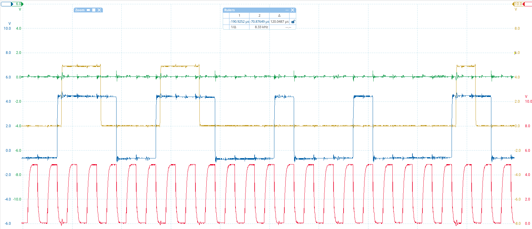
New insights: It must be a signal integrity issue where the LCDs can't get the data quite right. See this capture. Red is clock, blue is data input, brown is data output, green is latch (irrelevant here). I am sending the same data across the whole display so even thouth the output lags behind 10 characters (600 bits), it SHOULD be the same pattern. Every group of HIGH bits is shortened by one bit.
(also yay, finally managed to get my PicoScope to work in Linux. One less reason to boot up the old Windows install)
-
New insights: It must be a signal integrity issue where the LCDs can't get the data quite right. See this capture. Red is clock, blue is data input, brown is data output, green is latch (irrelevant here). I am sending the same data across the whole display so even thouth the output lags behind 10 characters (600 bits), it SHOULD be the same pattern. Every group of HIGH bits is shortened by one bit.
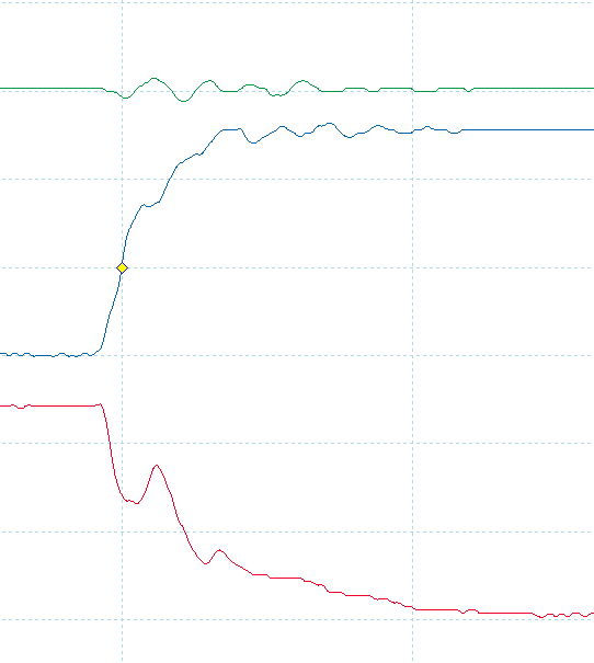
pretty sure the clock (red) shouldn't have hiccups like this
-
pretty sure the clock (red) shouldn't have hiccups like this
let's play around with some series termination
-
let's play around with some series termination
330R on both data and clock - data is acceptable, but clock is way too weak. It still registers though! Still showing garbage anyway. But now the data out doesn't keep losing bits

Gonna try 100R on clock and leave it at 330R for data.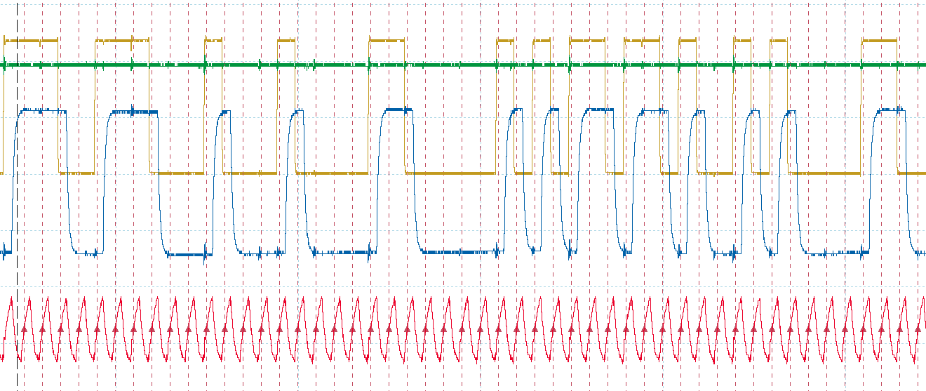
-
R relay@relay.infosec.exchange shared this topic
-
330R on both data and clock - data is acceptable, but clock is way too weak. It still registers though! Still showing garbage anyway. But now the data out doesn't keep losing bits
Gonna try 100R on clock and leave it at 330R for data.I extended my font generator thingy to allow the reverse operation, i.e. entering bytes and showing what they would look like on the LCD. I then added a function to shift the data bit by bit, and tried it with the character I am trying to send (5), and of course - one left shift and I get exactly the garbled characters I am seeing on the display. So that is what's happening. Somehow there is a single bit shift in all of the data
-
I extended my font generator thingy to allow the reverse operation, i.e. entering bytes and showing what they would look like on the LCD. I then added a function to shift the data bit by bit, and tried it with the character I am trying to send (5), and of course - one left shift and I get exactly the garbled characters I am seeing on the display. So that is what's happening. Somehow there is a single bit shift in all of the data
I did confirm with the oscilloscope that what the LCD is receiving is valid data now and that the data matches what it should be. So the bit shift must have occurred outside of the timeframe I sampled with the scope
-
I did confirm with the oscilloscope that what the LCD is receiving is valid data now and that the data matches what it should be. So the bit shift must have occurred outside of the timeframe I sampled with the scope
i.
i switched the clock phase (SPI mode 1 instead of 0)
and it works
i can't
-
i.
i switched the clock phase (SPI mode 1 instead of 0)
and it works
i can't
why?? I tested with Arduino's shiftOut weeks ago and it worked?? Isn't shiftOut also mode 0?
-
why?? I tested with Arduino's shiftOut weeks ago and it worked?? Isn't shiftOut also mode 0?
-
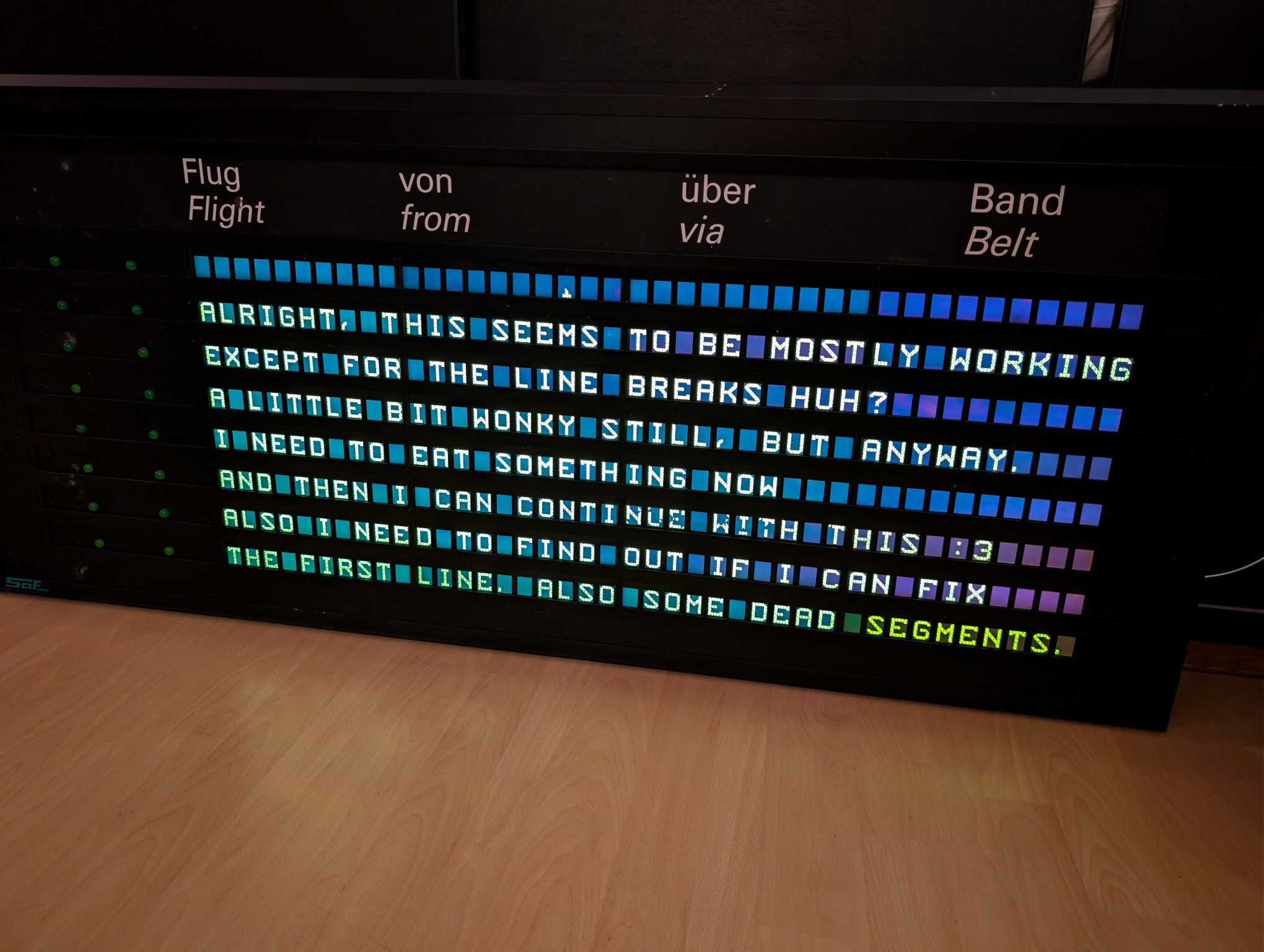
@cato happy eating :3
-
@cato happy eating :3
@Citali thanks
-
@cato good noms, why is the last word orangy?
-
@cato good noms, why is the last word orangy?
@mist yeah no idea, seems like that module might have been replaced and has a slightly different tone
-
@cato This is so cool!
-
@cato This is so cool!
@thiccpaws thank you! :3
-
Next problem: The alternating blinkers next to each row seem to not turn off fully. I already identified this as being caused by the fluorescent tubes inside the display radiating into the ribbon cables (they're just kinda loose inside) and my board missing pulldown resistors. My blinker control uses two shift registers with parallel data but opposite output enables to alternate between left and right and I forgot that enable = low means high-impedance, not low outputs.
Pulldown resistors fixed that too!
Next: Fix the broken first row - turns out this was just some broken solder joints. Easy fix. The soldering quality in this display is shockingly poor. But it was a lab / development device after all.
Also gave it a good clean, looks much nicer now!
Now all that's left to do is replace the little potentiometer with a proper brightnes ssensor and wire my board up to the ballasts for dimming.