Time to dust off this thread!
-
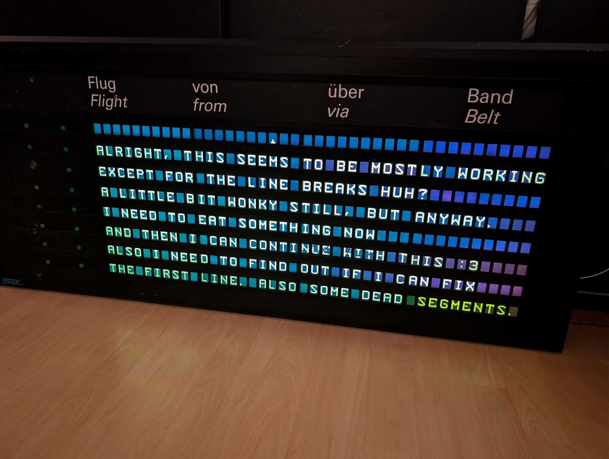
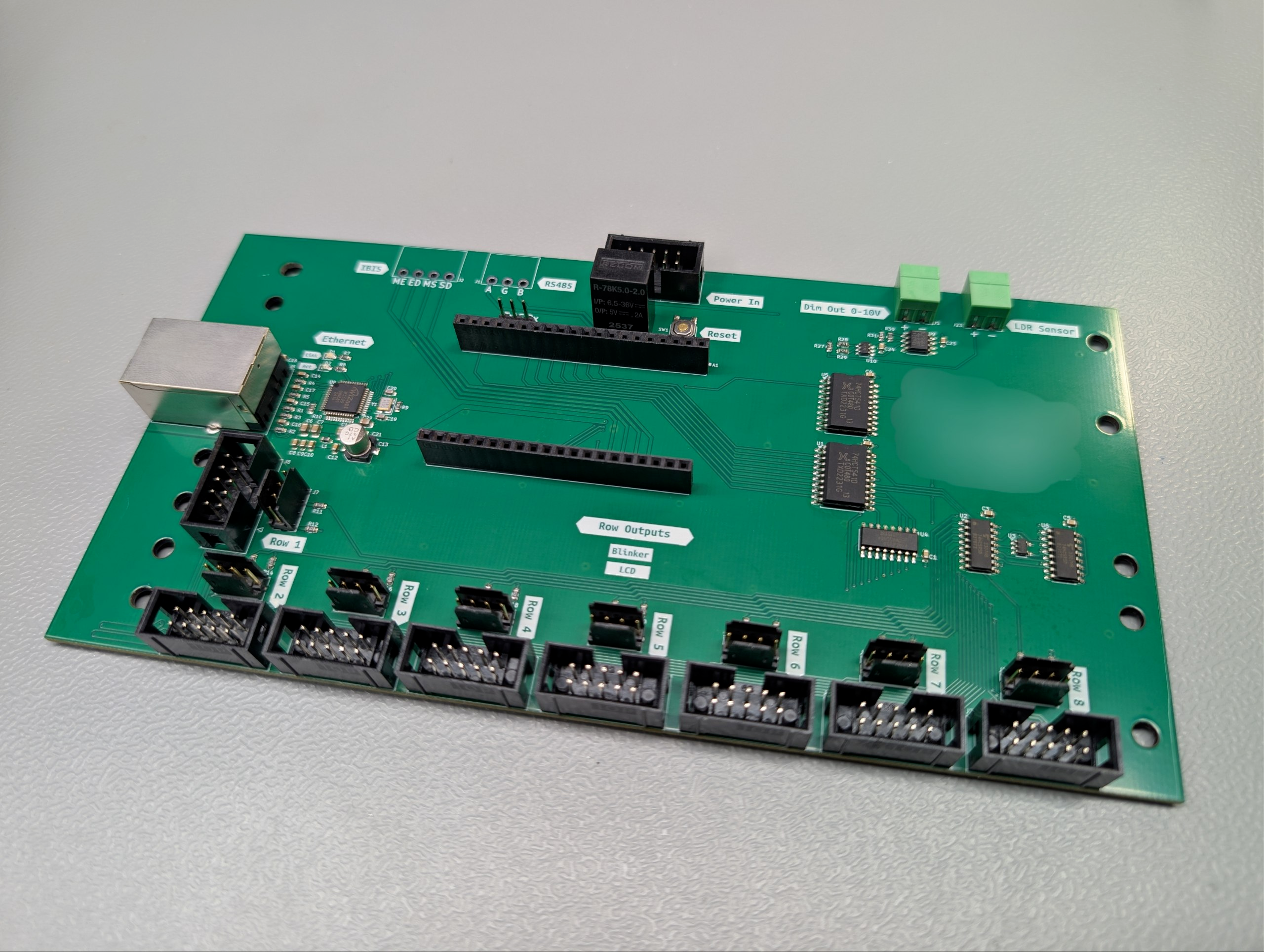
There it is! It can control all 8 rows of LCDs and the alternating indicators that are left of each line of text.
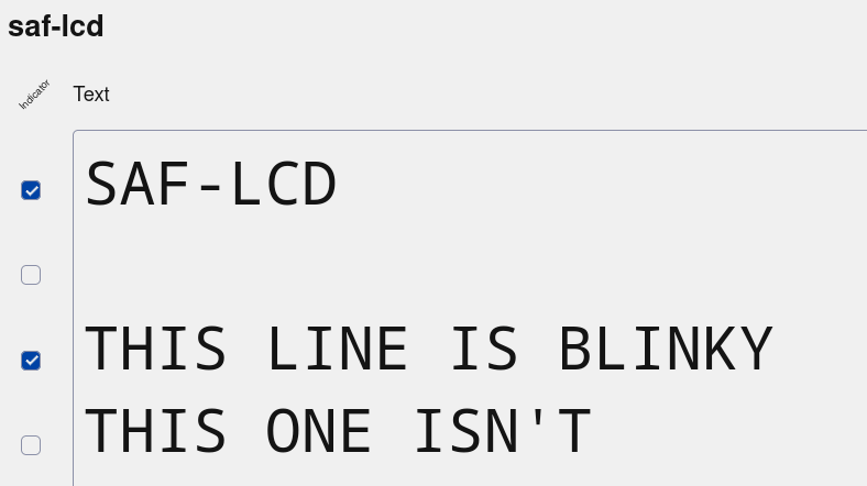
I added a "line flags" feature to my software - basically a uint8_t with up to 8 flag bits per line of text that can be used for the indicators or whatever else a display might hold in the future. My web frontend automatically renders these as checkboxes based on the display configuration.
-
I added a "line flags" feature to my software - basically a uint8_t with up to 8 flag bits per line of text that can be used for the indicators or whatever else a display might hold in the future. My web frontend automatically renders these as checkboxes based on the display configuration.
Since this display is using mosaic segmented LCDs, creating the font data would be a huge pain in the butt to do by just writing down raw bytes. So I made a quick and dirty little tool by tracing a photo of the LCD layout in Inkscape, using this in a HTML file with some JavaScript to make it interactive and having that spit out the correct bytes for the drawn character.
-
Since this display is using mosaic segmented LCDs, creating the font data would be a huge pain in the butt to do by just writing down raw bytes. So I made a quick and dirty little tool by tracing a photo of the LCD layout in Inkscape, using this in a HTML file with some JavaScript to make it interactive and having that spit out the correct bytes for the drawn character.
Fun fact! This thing is using 60 bits per character. No, it doesn't use any padding in between. I had to do some annoying bit shifting to get a nice data stream.
-
Fun fact! This thing is using 60 bits per character. No, it doesn't use any padding in between. I had to do some annoying bit shifting to get a nice data stream.
Font done, bootup shows the hostname and IP (as much as fits on a single module at least). Exactly as it should be!
-
Font done, bootup shows the hostname and IP (as much as fits on a single module at least). Exactly as it should be!
The alternating blinker control also works!
-
The alternating blinker control also works!
Aaaand I'm in integration hell

-
Aaaand I'm in integration hell
There seems to be some sort of problem once more than 4 LCD buses are plugged in. But measuring the shared signal lines, the signal levels and edges as well as the power rails look totally fine, so it's not just the driver being too weak...?
It fails in a repeatable, consistent way too, so random glitches seem very unlikely.
Even at a comically slow 5 kHz clock it still fails.
But enough for today, I really need to sleep
-
There seems to be some sort of problem once more than 4 LCD buses are plugged in. But measuring the shared signal lines, the signal levels and edges as well as the power rails look totally fine, so it's not just the driver being too weak...?
It fails in a repeatable, consistent way too, so random glitches seem very unlikely.
Even at a comically slow 5 kHz clock it still fails.
But enough for today, I really need to sleep@cato without knowing the circuity; do they may interfere via ground/chassis?
Where do you measure the signals: next to the source or next to the sink?
Are the glitches also present while measuring?
How do you even measure? What propes do you use?(Don't expect an expert discussion from me – those are merely ideas where i would suspected sources of errors while not knowing anything)
-
@cato without knowing the circuity; do they may interfere via ground/chassis?
Where do you measure the signals: next to the source or next to the sink?
Are the glitches also present while measuring?
How do you even measure? What propes do you use?(Don't expect an expert discussion from me – those are merely ideas where i would suspected sources of errors while not knowing anything)
@Foxotronic yeah I measured at the source because it's easier but I was pretty tired, I'll do some more measurements today. Can't say if it happens while measuring yet
-
There seems to be some sort of problem once more than 4 LCD buses are plugged in. But measuring the shared signal lines, the signal levels and edges as well as the power rails look totally fine, so it's not just the driver being too weak...?
It fails in a repeatable, consistent way too, so random glitches seem very unlikely.
Even at a comically slow 5 kHz clock it still fails.
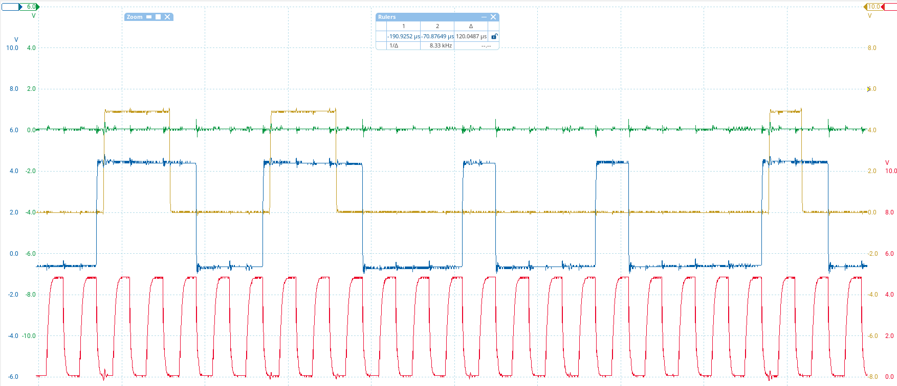
But enough for today, I really need to sleepNew insights: It must be a signal integrity issue where the LCDs can't get the data quite right. See this capture. Red is clock, blue is data input, brown is data output, green is latch (irrelevant here). I am sending the same data across the whole display so even thouth the output lags behind 10 characters (600 bits), it SHOULD be the same pattern. Every group of HIGH bits is shortened by one bit.
-
New insights: It must be a signal integrity issue where the LCDs can't get the data quite right. See this capture. Red is clock, blue is data input, brown is data output, green is latch (irrelevant here). I am sending the same data across the whole display so even thouth the output lags behind 10 characters (600 bits), it SHOULD be the same pattern. Every group of HIGH bits is shortened by one bit.
(also yay, finally managed to get my PicoScope to work in Linux. One less reason to boot up the old Windows install)
-
New insights: It must be a signal integrity issue where the LCDs can't get the data quite right. See this capture. Red is clock, blue is data input, brown is data output, green is latch (irrelevant here). I am sending the same data across the whole display so even thouth the output lags behind 10 characters (600 bits), it SHOULD be the same pattern. Every group of HIGH bits is shortened by one bit.
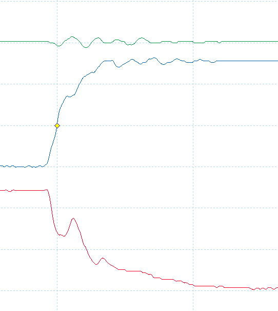
pretty sure the clock (red) shouldn't have hiccups like this
-
pretty sure the clock (red) shouldn't have hiccups like this
let's play around with some series termination
-
let's play around with some series termination
330R on both data and clock - data is acceptable, but clock is way too weak. It still registers though! Still showing garbage anyway. But now the data out doesn't keep losing bits

Gonna try 100R on clock and leave it at 330R for data.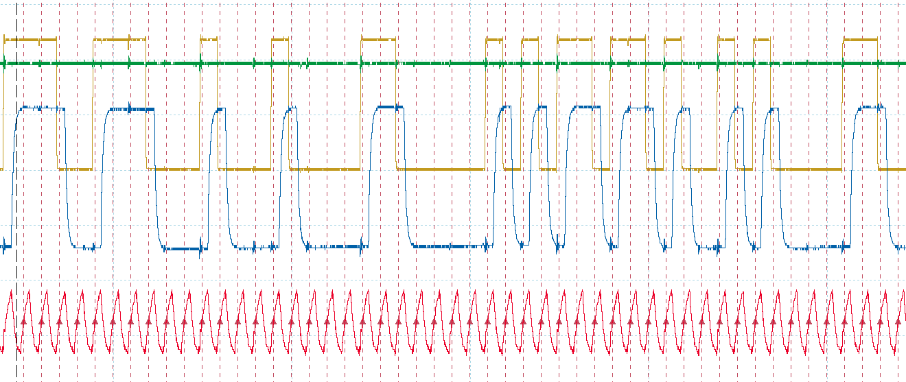
-
R relay@relay.infosec.exchange shared this topic
-
330R on both data and clock - data is acceptable, but clock is way too weak. It still registers though! Still showing garbage anyway. But now the data out doesn't keep losing bits
Gonna try 100R on clock and leave it at 330R for data.I extended my font generator thingy to allow the reverse operation, i.e. entering bytes and showing what they would look like on the LCD. I then added a function to shift the data bit by bit, and tried it with the character I am trying to send (5), and of course - one left shift and I get exactly the garbled characters I am seeing on the display. So that is what's happening. Somehow there is a single bit shift in all of the data
-
I extended my font generator thingy to allow the reverse operation, i.e. entering bytes and showing what they would look like on the LCD. I then added a function to shift the data bit by bit, and tried it with the character I am trying to send (5), and of course - one left shift and I get exactly the garbled characters I am seeing on the display. So that is what's happening. Somehow there is a single bit shift in all of the data
I did confirm with the oscilloscope that what the LCD is receiving is valid data now and that the data matches what it should be. So the bit shift must have occurred outside of the timeframe I sampled with the scope
-
I did confirm with the oscilloscope that what the LCD is receiving is valid data now and that the data matches what it should be. So the bit shift must have occurred outside of the timeframe I sampled with the scope
i.
i switched the clock phase (SPI mode 1 instead of 0)
and it works
i can't
-
i.
i switched the clock phase (SPI mode 1 instead of 0)
and it works
i can't
why?? I tested with Arduino's shiftOut weeks ago and it worked?? Isn't shiftOut also mode 0?
-
why?? I tested with Arduino's shiftOut weeks ago and it worked?? Isn't shiftOut also mode 0?
-
@cato happy eating :3