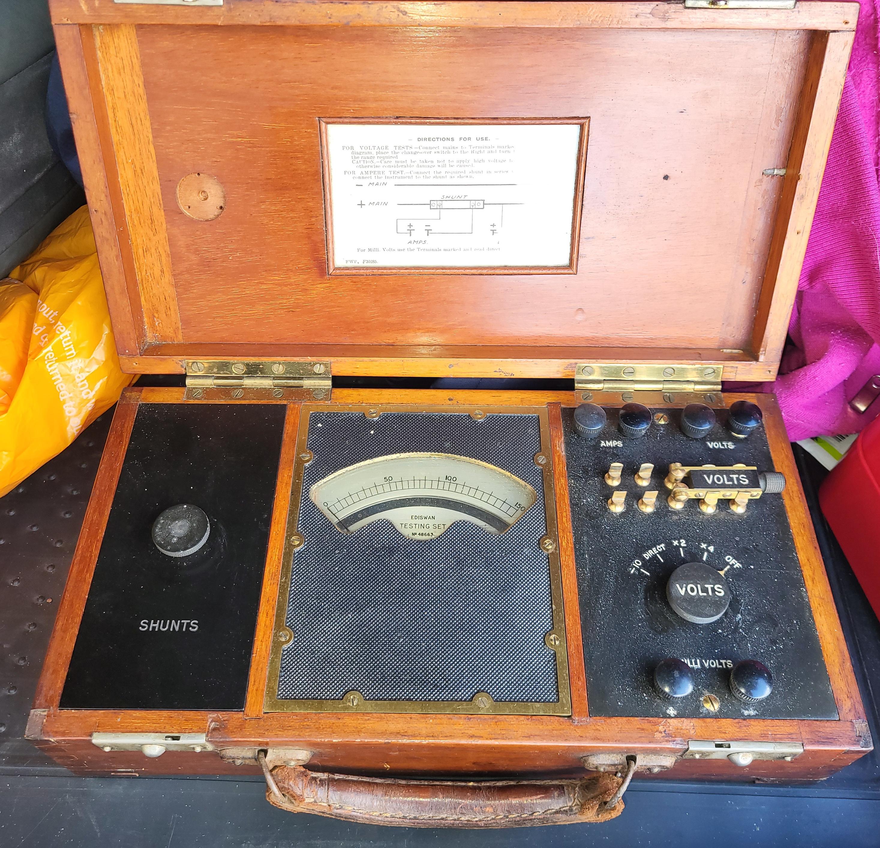
Went for breakfast this morning, and returned with one of those old fangled multimeters.
-
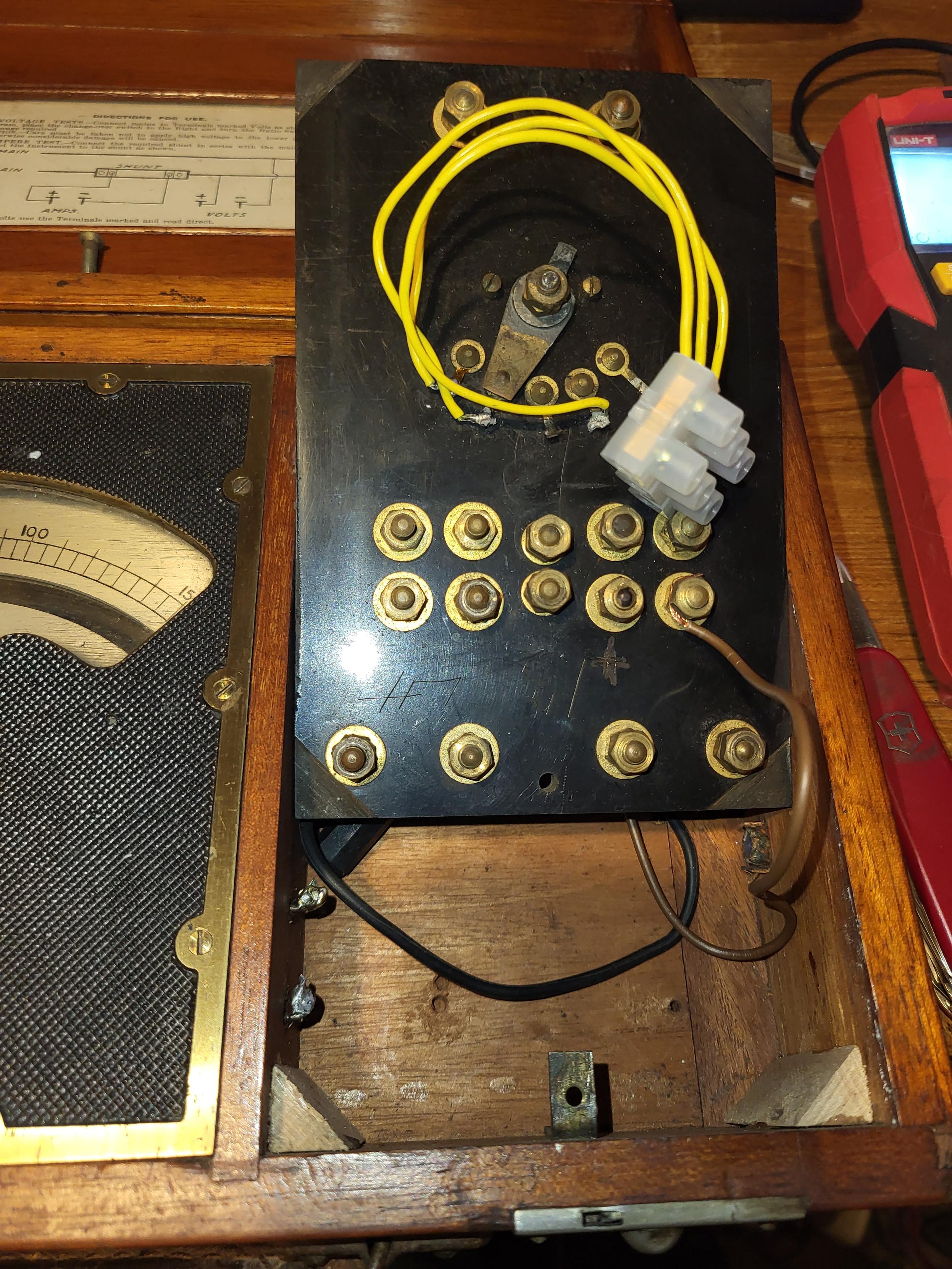
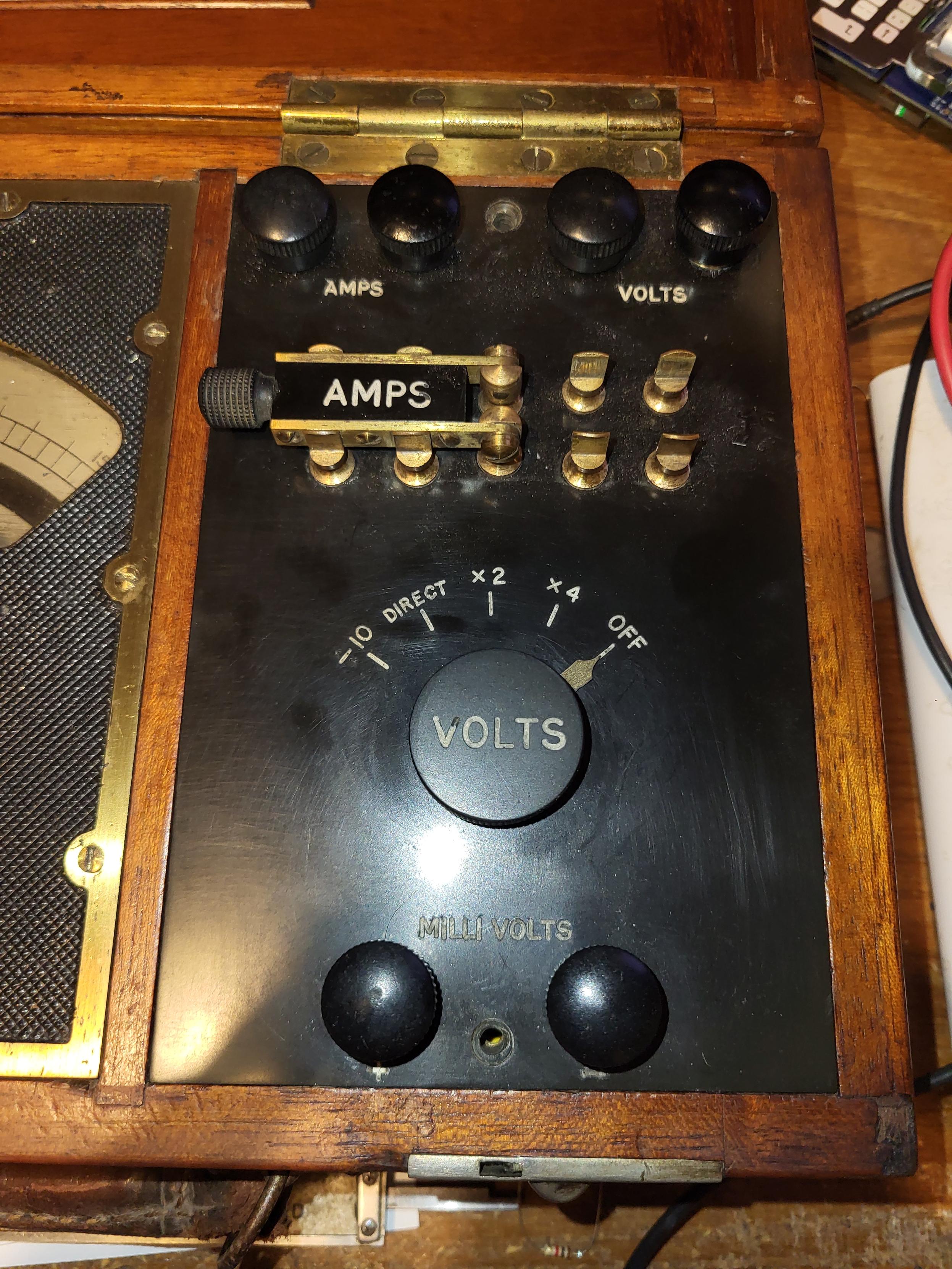
At first look, the insides are not what i expected... not at all...
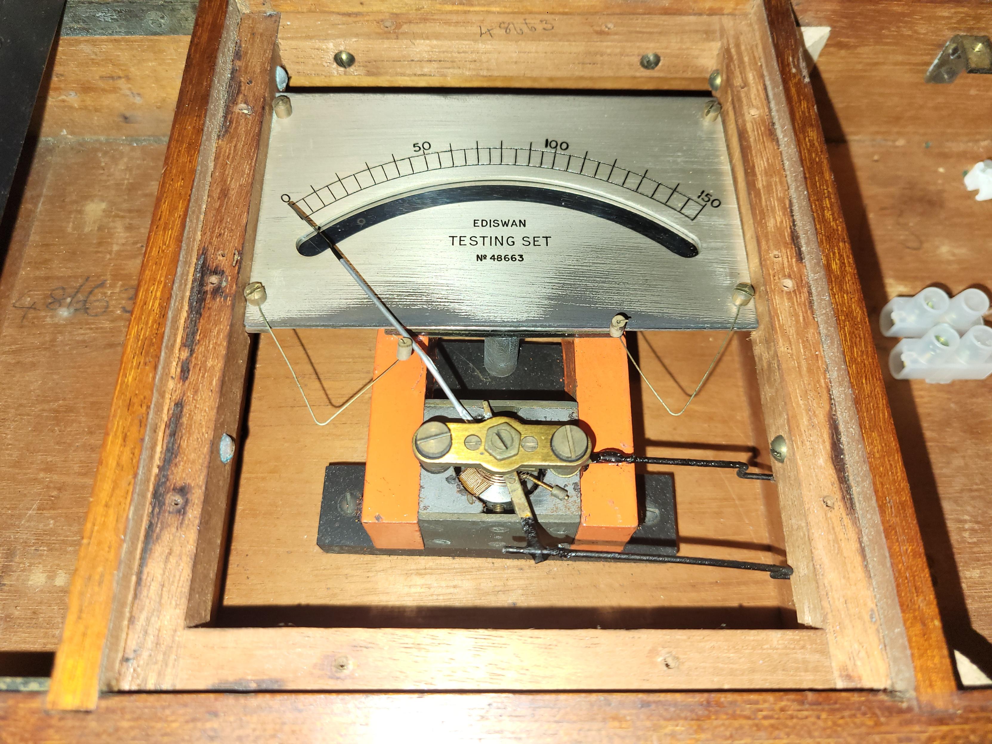
At least the meter looks untampered with, although not working and a dubiously low resistance.
-
At least the meter looks untampered with, although not working and a dubiously low resistance.
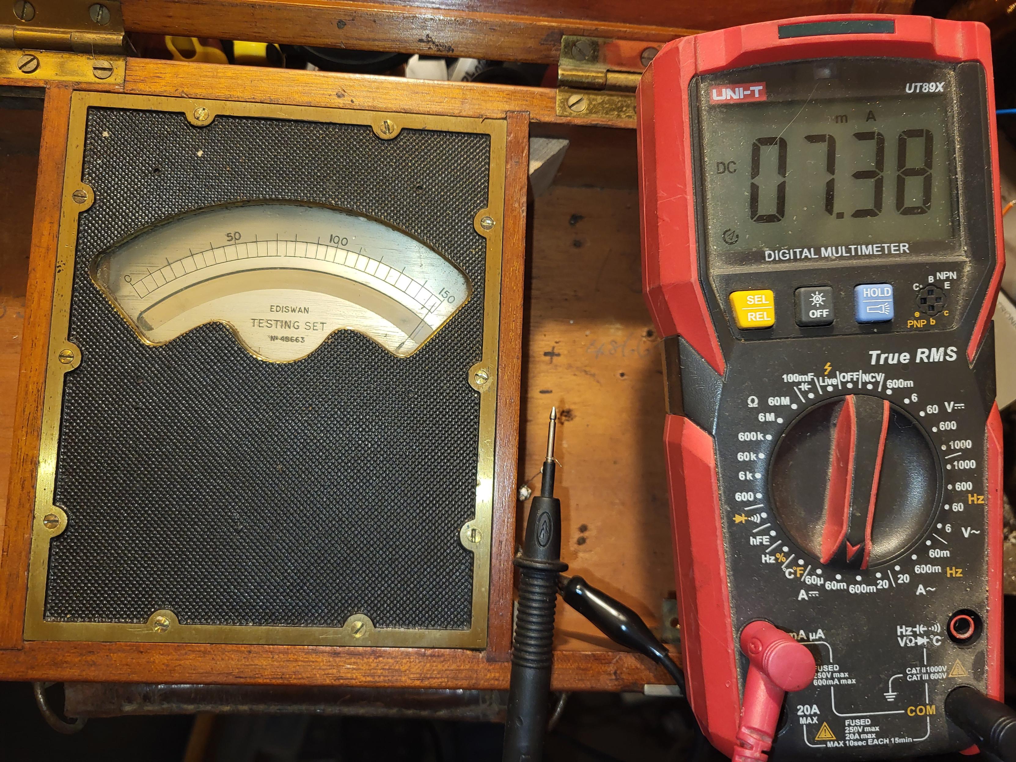
A bit of a clean and the meter works, 7.4mA for full scale. It does explain the low resistance. You forget how insensitive early meters were. I also suspect the magnets in the movement might not be what they once were.
-
At first look, the insides are not what i expected... not at all...
@Extelec oh no, vintage choc block


 ️
️ -
A bit of a clean and the meter works, 7.4mA for full scale. It does explain the low resistance. You forget how insensitive early meters were. I also suspect the magnets in the movement might not be what they once were.
I've worked out the Voltage scales.
Off
0-600v x4
0-300v x2
0-150v direct
0-15v /10
and 0-150mV for the Mili-volt connection.They should just be a matter of getting the right resistor values, and rewiring.
Current is a guess, but I'll go for 0-1.5A without shunt. As this will be a useful range, no other reason.
This could change, IF I get more information on the set.
-
@Extelec oh no, vintage choc block
️@hackhitchin Precisely ...
-
I've worked out the Voltage scales.
Off
0-600v x4
0-300v x2
0-150v direct
0-15v /10
and 0-150mV for the Mili-volt connection.They should just be a matter of getting the right resistor values, and rewiring.
Current is a guess, but I'll go for 0-1.5A without shunt. As this will be a useful range, no other reason.
This could change, IF I get more information on the set.
A rough plan for replacing the Innards of the meter.
Suggestions on appropriate (for its age) resistor types welcome.
As is any reference to this meters existence.
I know the company, I know it's not a transistor tester (I suspect valve era) , but the internet comes up blank.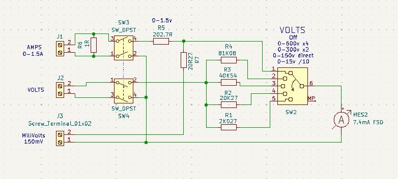
-
A rough plan for replacing the Innards of the meter.
Suggestions on appropriate (for its age) resistor types welcome.
As is any reference to this meters existence.
I know the company, I know it's not a transistor tester (I suspect valve era) , but the internet comes up blank.@Extelec hand-wound bobbin-type resistors, as in very old AVOs?
-
A rough plan for replacing the Innards of the meter.
Suggestions on appropriate (for its age) resistor types welcome.
As is any reference to this meters existence.
I know the company, I know it's not a transistor tester (I suspect valve era) , but the internet comes up blank.@Extelec
Does the outside of the case have any identification plates or disks? Looks like some of the ediswan instruments had a brass disk with a model number on them. -
@Extelec
Does the outside of the case have any identification plates or disks? Looks like some of the ediswan instruments had a brass disk with a model number on them.@bodluricon no not at all, the only reference is on the movement itself.

-
@bodluricon no not at all, the only reference is on the movement itself.
-
@bodluricon Thank you, great find!
Shame there isn't more info.
-
A rough plan for replacing the Innards of the meter.
Suggestions on appropriate (for its age) resistor types welcome.
As is any reference to this meters existence.
I know the company, I know it's not a transistor tester (I suspect valve era) , but the internet comes up blank.@Extelec I vaguely recall a bucket of water or oil used as a resistor for trams. The coil was raised from the bucket to go faster.
-
R relay@relay.mycrowd.ca shared this topic