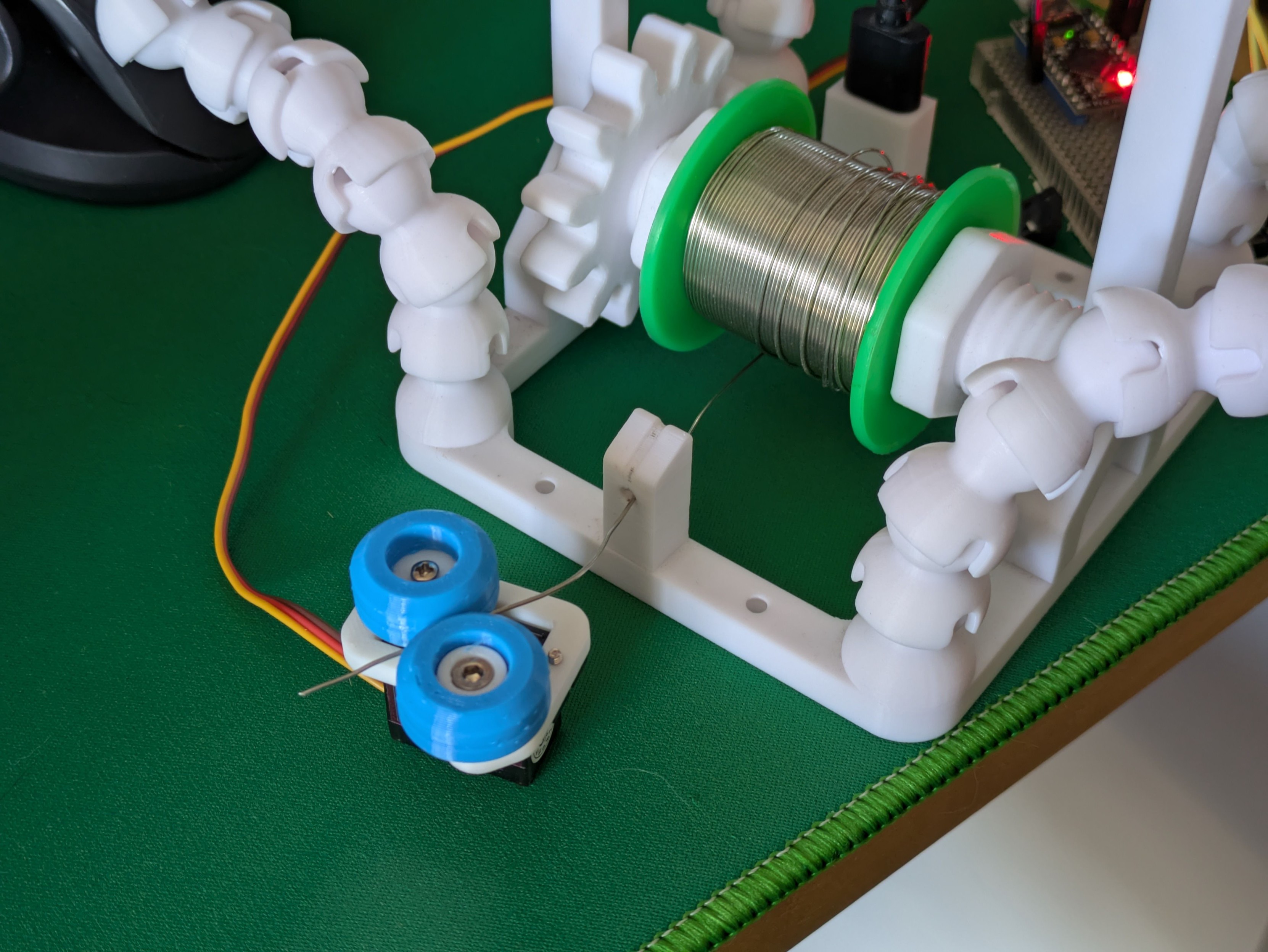
Proof of concept: A servo motor, a little platform with an opposing wheel, and two TPU tyres with a tiny groove down the middle will very capably grab a length of solder and push/pull it.
-
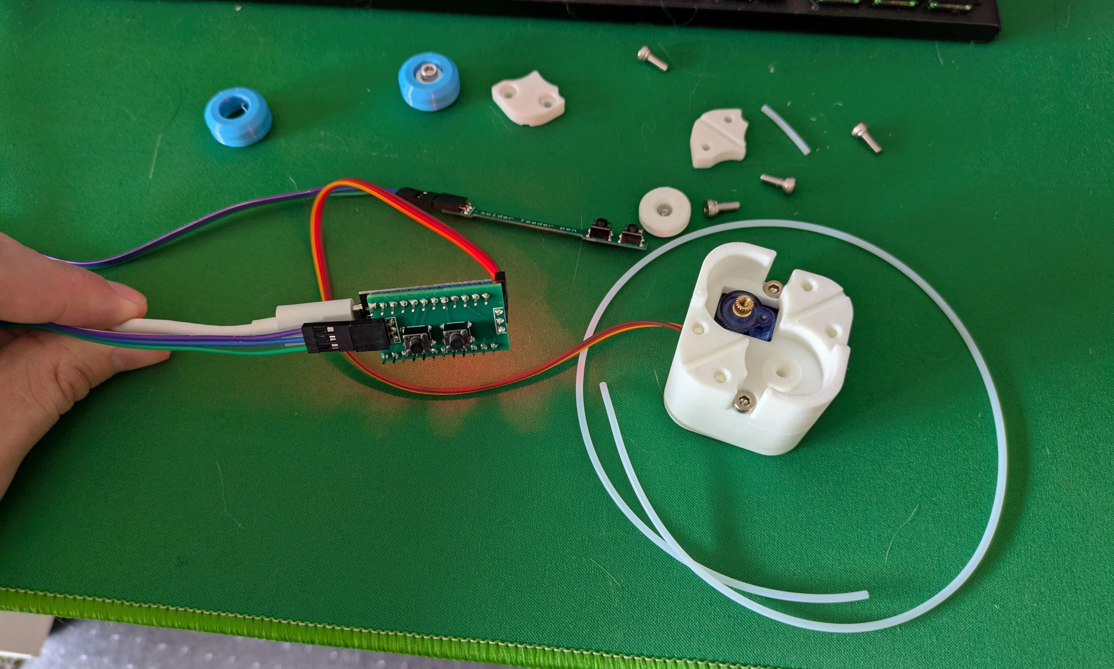
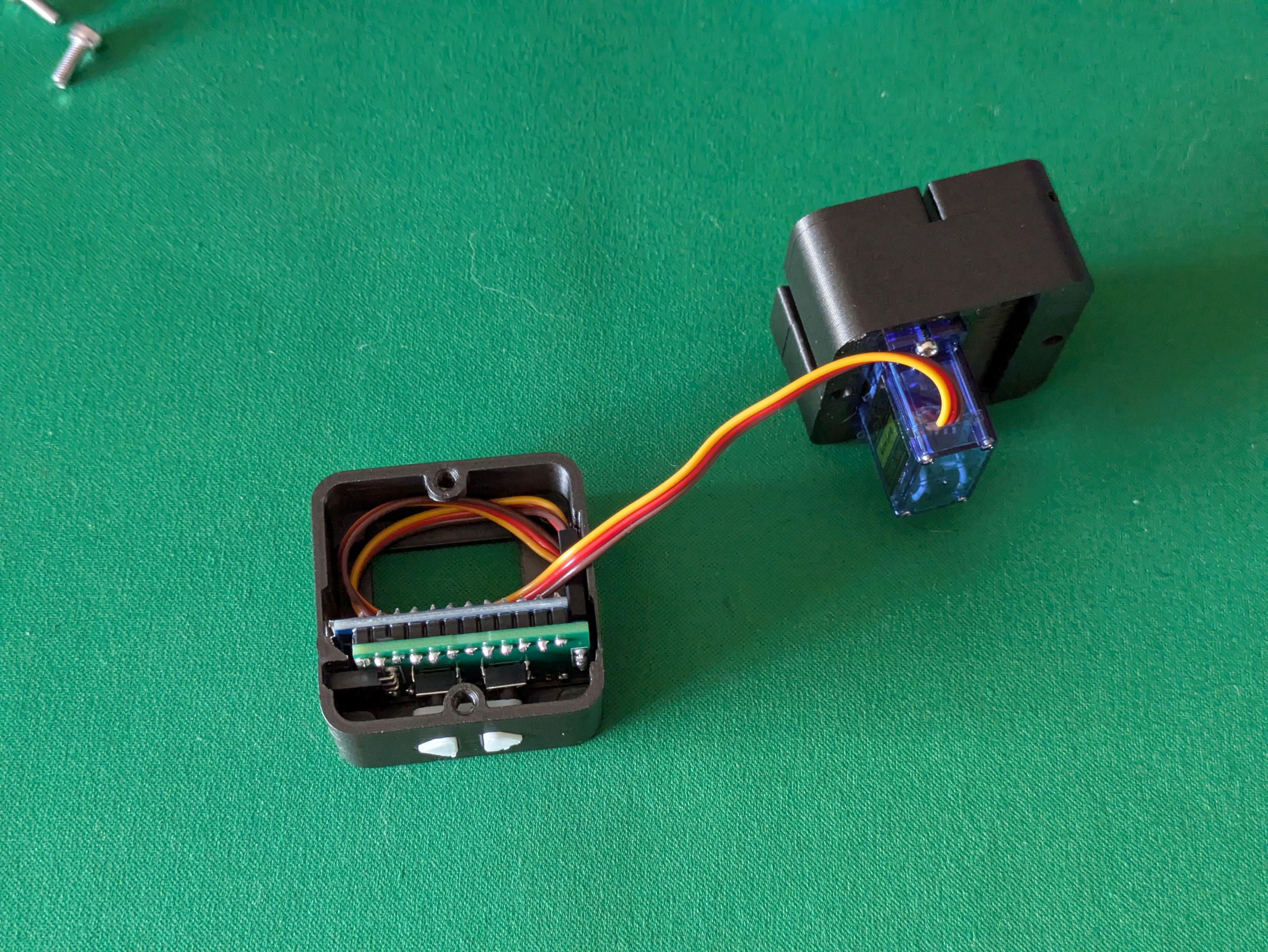
Continuous rotation servo + a 608 size bearing and TPU wheels + PTFE tubing + fewer 3D printed parts than you'd think + actually securing this contraption to my soldering station = a computer-controlled power feed for solder wire, for those long electronics assembly sessions.
Even before starting on the second part (the actual pen with buttons you hold at the other end of the tube) this is a serious project milestone and I'm very happy with it. #maker #3DPrinting #SolderingStation
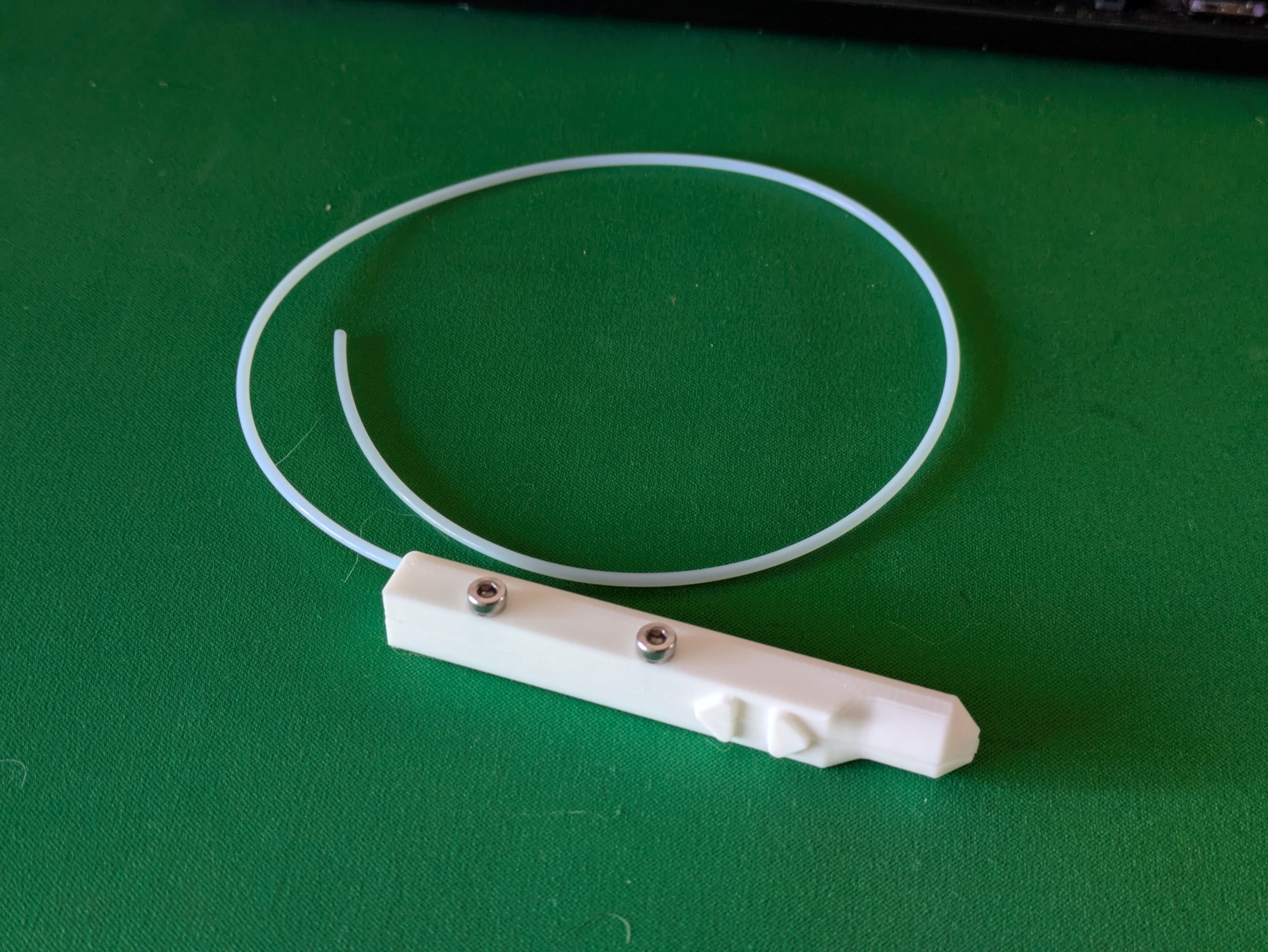
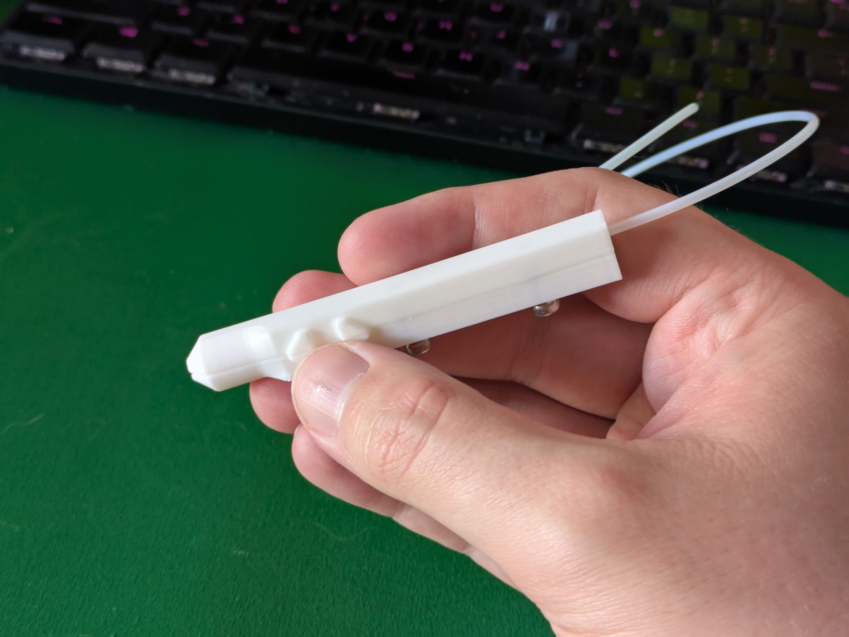
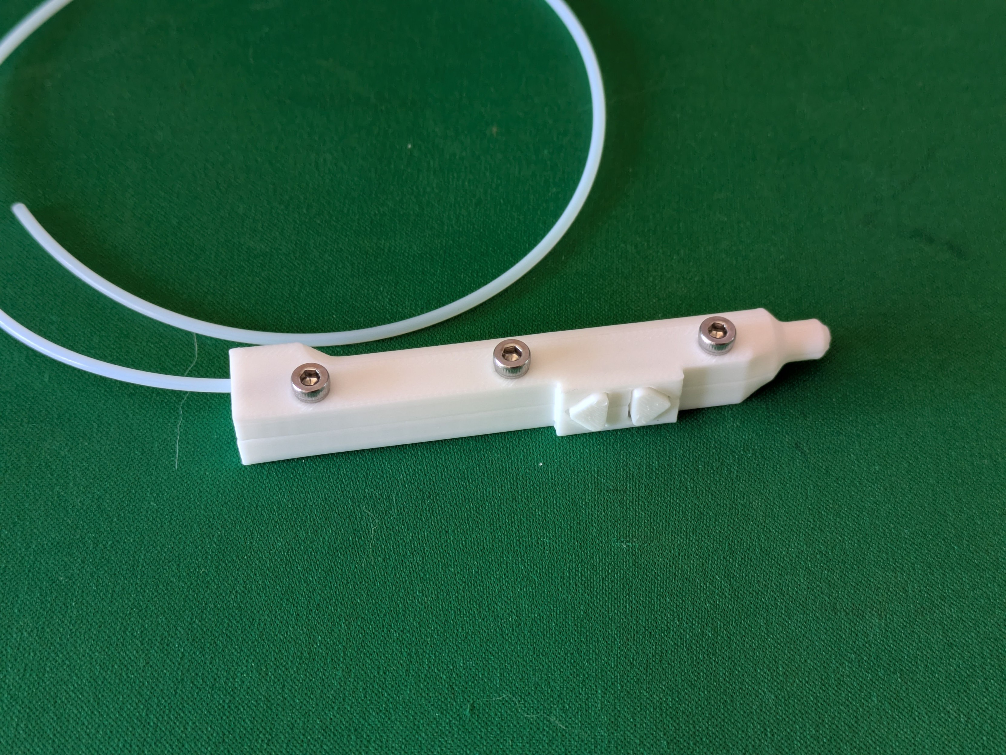
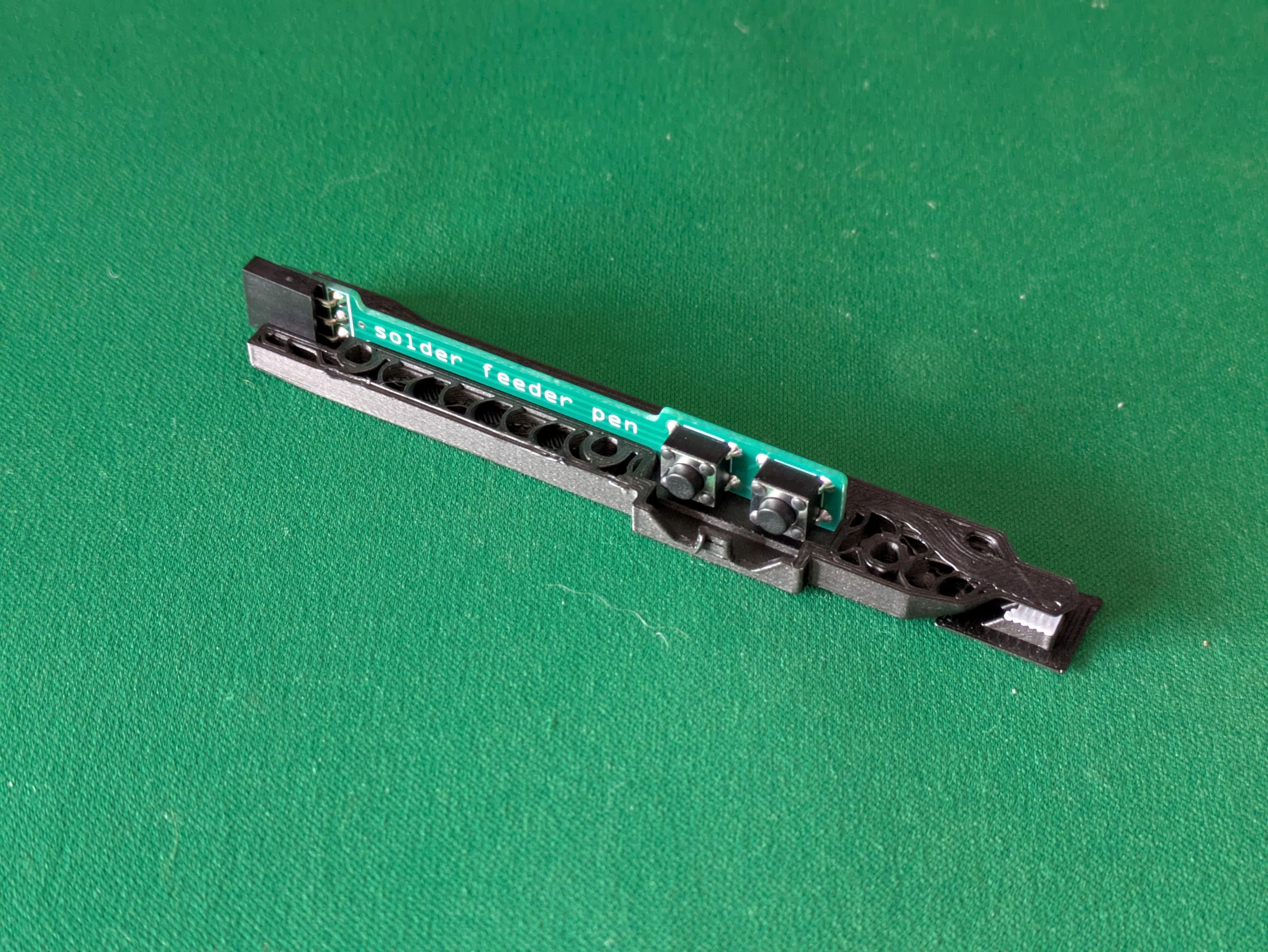
A first pass at the shape of the solder pen itself. A 1.25mm diameter pipe through the body of the pen allows for the PTFE tube to be threaded in easily.
A cutout for a very slim PCB with two tactile buttons and a 3-pin header will also run through most of the pen - currently the buttons are just solid to get a feel for it in the hand.
-
A first pass at the shape of the solder pen itself. A 1.25mm diameter pipe through the body of the pen allows for the PTFE tube to be threaded in easily.
A cutout for a very slim PCB with two tactile buttons and a 3-pin header will also run through most of the pen - currently the buttons are just solid to get a feel for it in the hand.
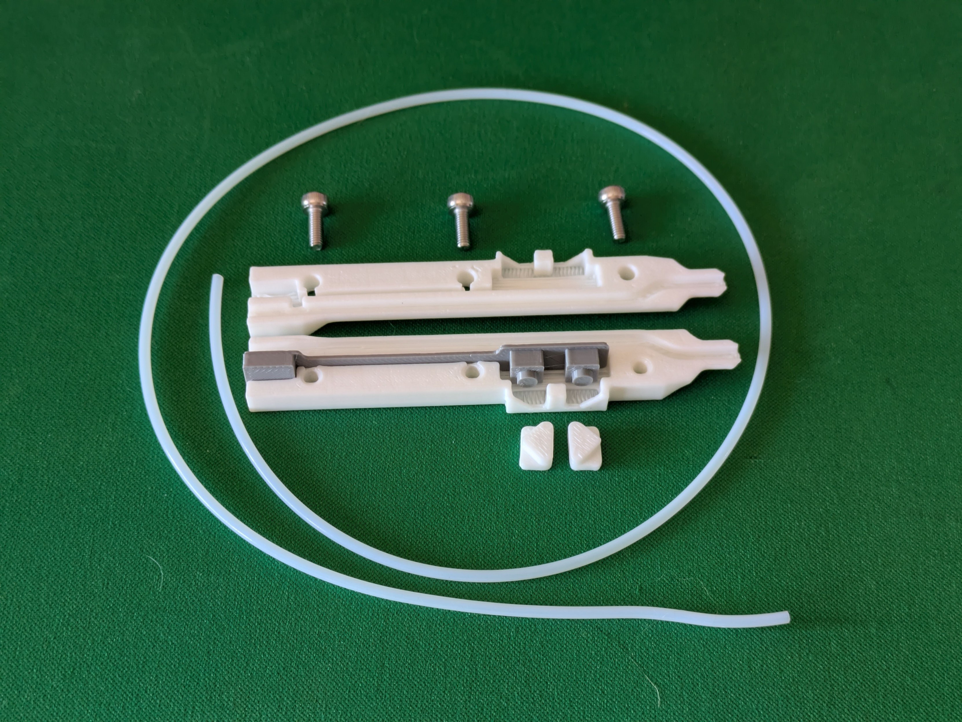
Behold: the prototype solder feeder pen, and the parts it's made up of. The grey bit is a facsimile of the circuit board I've designed to slot in here - it just routes two tactile buttons to a three pin socket (one to each button with a pullup resistor in the microcontroller, and a common ground).
The thinnest PCB that JLC will sell me without charging me more is 0.8mm, so there's a 1mm clearance in the print for it to slot in securely.
Time to order some electronics!
-
Behold: the prototype solder feeder pen, and the parts it's made up of. The grey bit is a facsimile of the circuit board I've designed to slot in here - it just routes two tactile buttons to a three pin socket (one to each button with a pullup resistor in the microcontroller, and a common ground).
The thinnest PCB that JLC will sell me without charging me more is 0.8mm, so there's a 1mm clearance in the print for it to slot in securely.
Time to order some electronics!
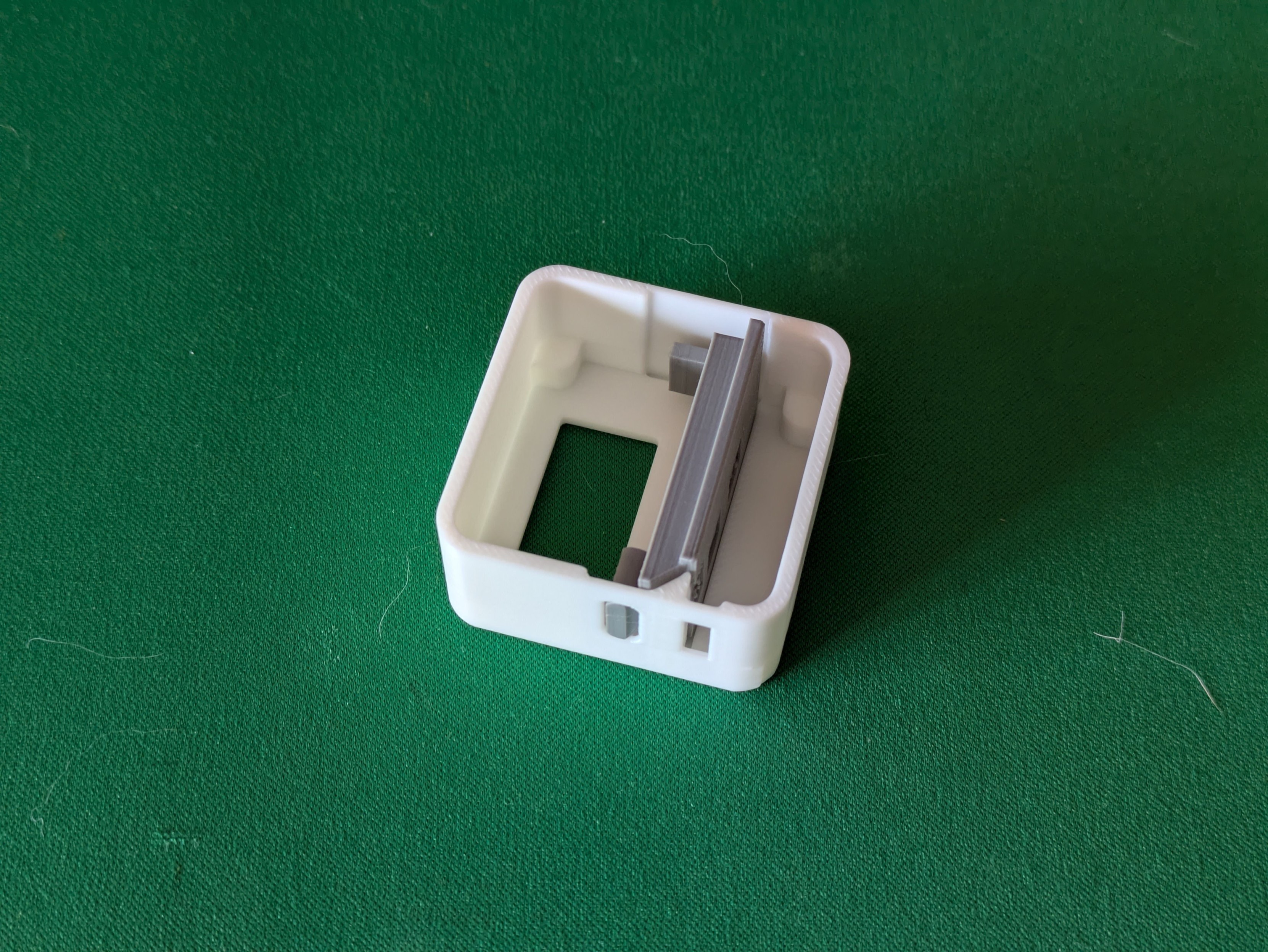
Printed another simulacra, this time of what I think the mainboard in my solder feeder will look like, and test-fitted it in an experimental base.
I need to squish a Pro Micro clone, two tactile buttons, a connector for the pen electronics and another one internally for the servo into one half of the base (the other half is mostly servo body) - I'm pretty happy with how this prototype slots and locks in.
-
Printed another simulacra, this time of what I think the mainboard in my solder feeder will look like, and test-fitted it in an experimental base.
I need to squish a Pro Micro clone, two tactile buttons, a connector for the pen electronics and another one internally for the servo into one half of the base (the other half is mostly servo body) - I'm pretty happy with how this prototype slots and locks in.
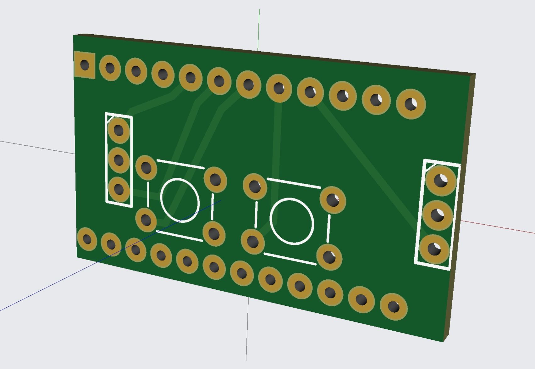
Have now designed and ordered the main PCB for my solder feeder. It's entirely unlabeled because my SVG outline didn't appear for some reason but that won't stop this prototype from happening.
This PCB layout looks chaotic as hell, but it'll make sense once stuff's been soldered to it - it's double-sided and has to situate stuff in precise places in a very small box.
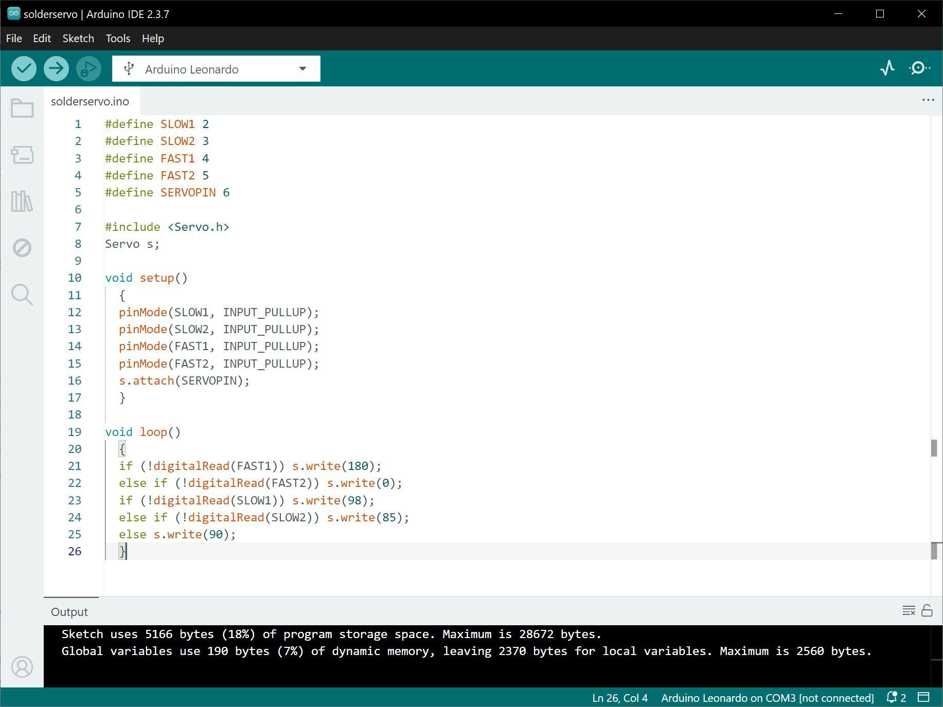
For my own benefit in a couple of weeks: Pen buttons are pins 2/3, main buttons are pins 4/5, servo is on pin 6.
-
Have now designed and ordered the main PCB for my solder feeder. It's entirely unlabeled because my SVG outline didn't appear for some reason but that won't stop this prototype from happening.
This PCB layout looks chaotic as hell, but it'll make sense once stuff's been soldered to it - it's double-sided and has to situate stuff in precise places in a very small box.
For my own benefit in a couple of weeks: Pen buttons are pins 2/3, main buttons are pins 4/5, servo is on pin 6.
I appear to have ordered some PCBs exactly at Chinese new year. I absolutely cannot begrudge them that so I guess this project gets shelved for a while longer than planned.
-
I appear to have ordered some PCBs exactly at Chinese new year. I absolutely cannot begrudge them that so I guess this project gets shelved for a while longer than planned.
Both sets of PCBs for this project are now in the mail. Might have to remember not to have any bright project ideas in February in future to avoid getting stymied by the Spring Festival.
-
Both sets of PCBs for this project are now in the mail. Might have to remember not to have any bright project ideas in February in future to avoid getting stymied by the Spring Festival.
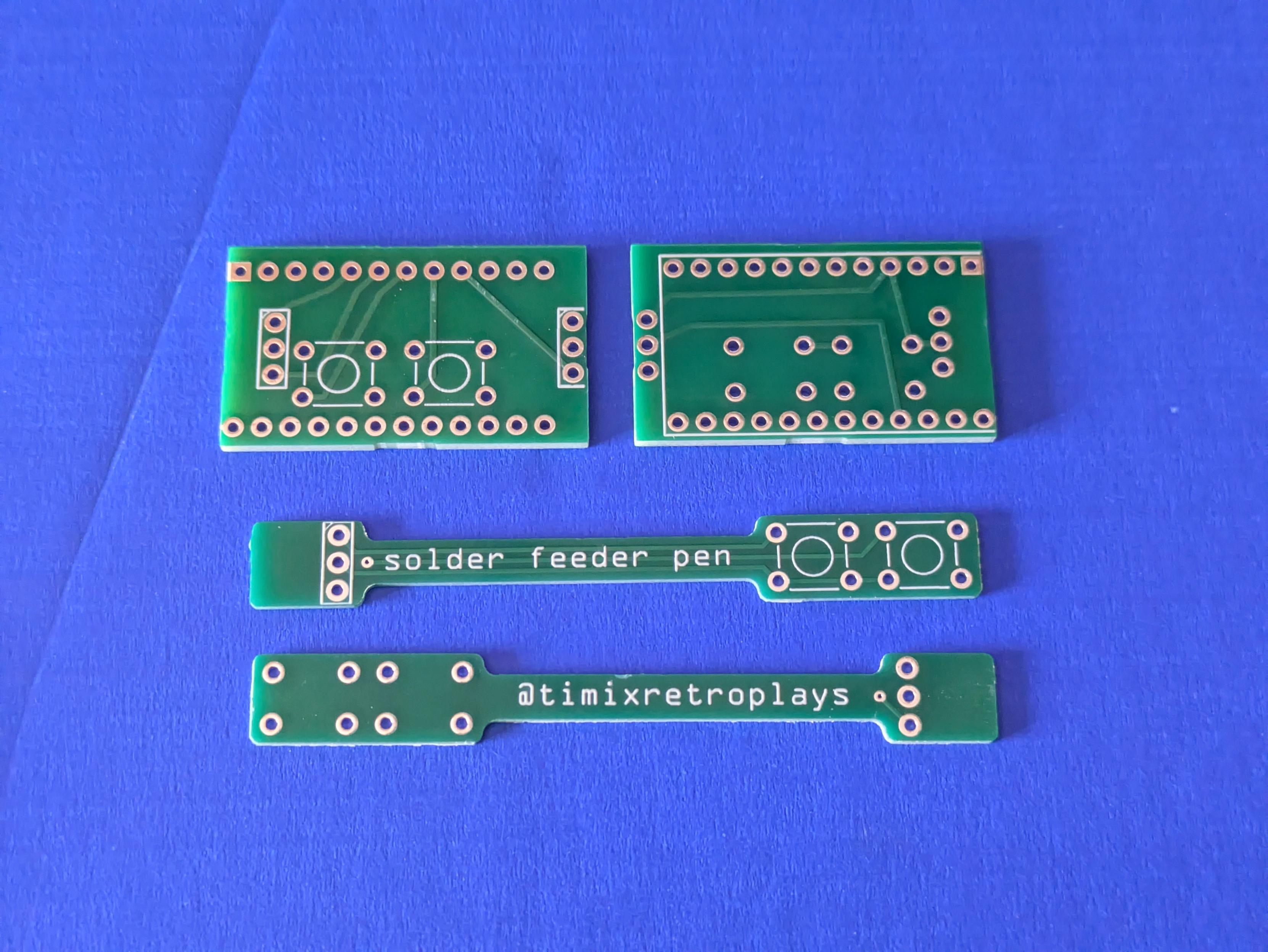
Success! Very small PCBs have arrived.
The long ones are 0.8mm thick - I think I could snap one if I wanted, but it's not going to happen by accident.
Also there are five of each and I bought plenty of everything else, so if anyone else in Australia thinks they might like a solder feeder pen, sing out.
-
Success! Very small PCBs have arrived.
The long ones are 0.8mm thick - I think I could snap one if I wanted, but it's not going to happen by accident.
Also there are five of each and I bought plenty of everything else, so if anyone else in Australia thinks they might like a solder feeder pen, sing out.
That moment you realise, just as the solder is cooling down on the very last component, that you made a mistake weeks ago and put the pad for a component on the wrong side of the board and prototype #1 is garbage without rework
-
That moment you realise, just as the solder is cooling down on the very last component, that you made a mistake weeks ago and put the pad for a component on the wrong side of the board and prototype #1 is garbage without rework
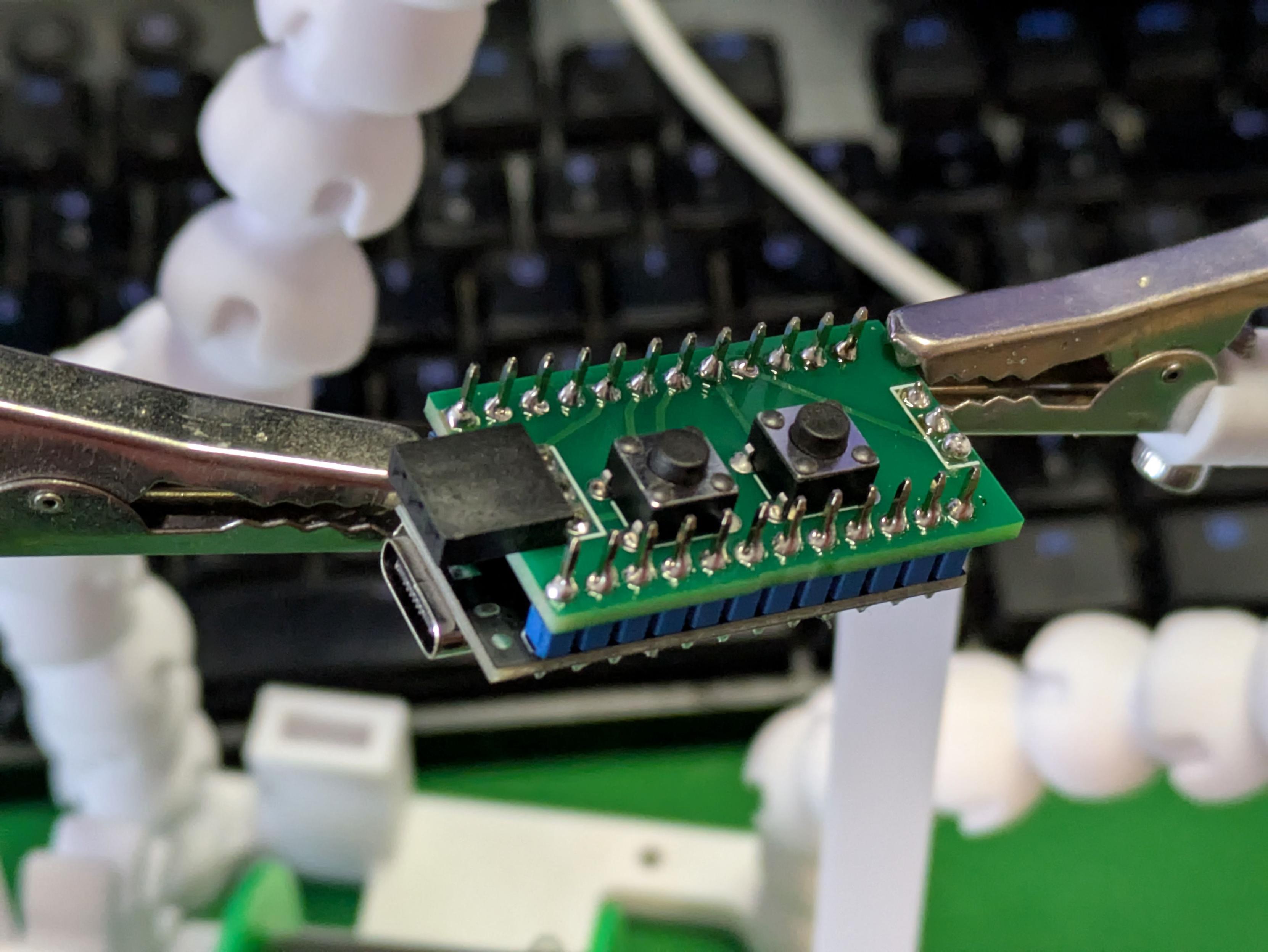
Not my best, not my worst - but for a V1.000 of something that is unreasonably crammed into as tiny a space as I could imagine, it's come together pretty well.
This is the mainboard for my solder feeder - the 3-pin socket near the Pro Micro's USB port is the connection out to the pen itself, the 3 pins at the back end go to the continuous rotation servo that actually moves stuff, and there are four buttons - the two on the main body will be for fast feeding, the two on the pen for slow.
-
Not my best, not my worst - but for a V1.000 of something that is unreasonably crammed into as tiny a space as I could imagine, it's come together pretty well.
This is the mainboard for my solder feeder - the 3-pin socket near the Pro Micro's USB port is the connection out to the pen itself, the 3 pins at the back end go to the continuous rotation servo that actually moves stuff, and there are four buttons - the two on the main body will be for fast feeding, the two on the pen for slow.
Well, the electronics seem to work correctly - all four buttons can make the servo run back and forth - but now there is a new problem: the servo suddenly looks and sounds underpowered, moving much more slowly than it did when everything was on the breadboard.
No code changes, and the extra electronics are just input-pullup buttons. Not sure why it'd behave differently now. A new spare servo acts exactly the same, and it's the same whether powered from VCC or RAW.
-
Well, the electronics seem to work correctly - all four buttons can make the servo run back and forth - but now there is a new problem: the servo suddenly looks and sounds underpowered, moving much more slowly than it did when everything was on the breadboard.
No code changes, and the extra electronics are just input-pullup buttons. Not sure why it'd behave differently now. A new spare servo acts exactly the same, and it's the same whether powered from VCC or RAW.
Now witness the power of this fully armed and operational solder feeder!
The power issue I think came down to a crappy Pro Micro clone board - another successfully flashed once and then permanently died, so the one in this short clip is actually the third one I've tried. It also sometimes cuts out until it's power cycled - I think it's overloading a cheap 5V regulator, version 2 will be powered from RAW rather than VCC.
This Works. Time to finish the enclosure. #3DPrinting #Electronics
-
Now witness the power of this fully armed and operational solder feeder!
The power issue I think came down to a crappy Pro Micro clone board - another successfully flashed once and then permanently died, so the one in this short clip is actually the third one I've tried. It also sometimes cuts out until it's power cycled - I think it's overloading a cheap 5V regulator, version 2 will be powered from RAW rather than VCC.
This Works. Time to finish the enclosure. #3DPrinting #Electronics
The code for this thing is dead simple - it reads from four buttons, then an if-then-else tree says what the servo does.
A regular servo gets commanded to positions expressed in degrees - 0 is fully one way, 90 centred, 180 fully the other. A continuous rotation servo like this one takes the same commands, but those values become relative speeds - so zero and 180 are full speed one way or the other, and 98 and 85 are the closest values I could get working for the slow feed option. #Arduino
-
The code for this thing is dead simple - it reads from four buttons, then an if-then-else tree says what the servo does.
A regular servo gets commanded to positions expressed in degrees - 0 is fully one way, 90 centred, 180 fully the other. A continuous rotation servo like this one takes the same commands, but those values become relative speeds - so zero and 180 are full speed one way or the other, and 98 and 85 are the closest values I could get working for the slow feed option. #Arduino
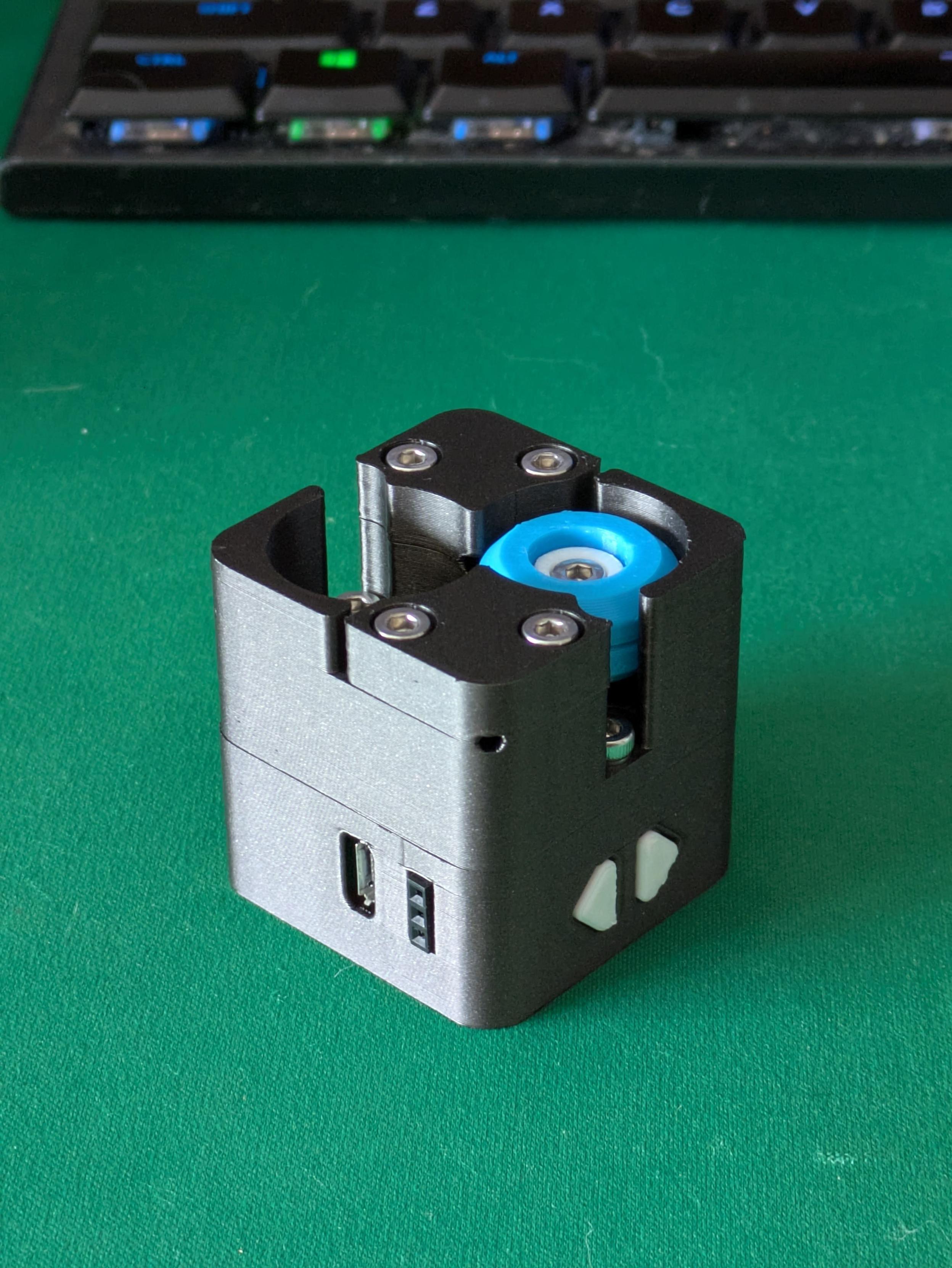
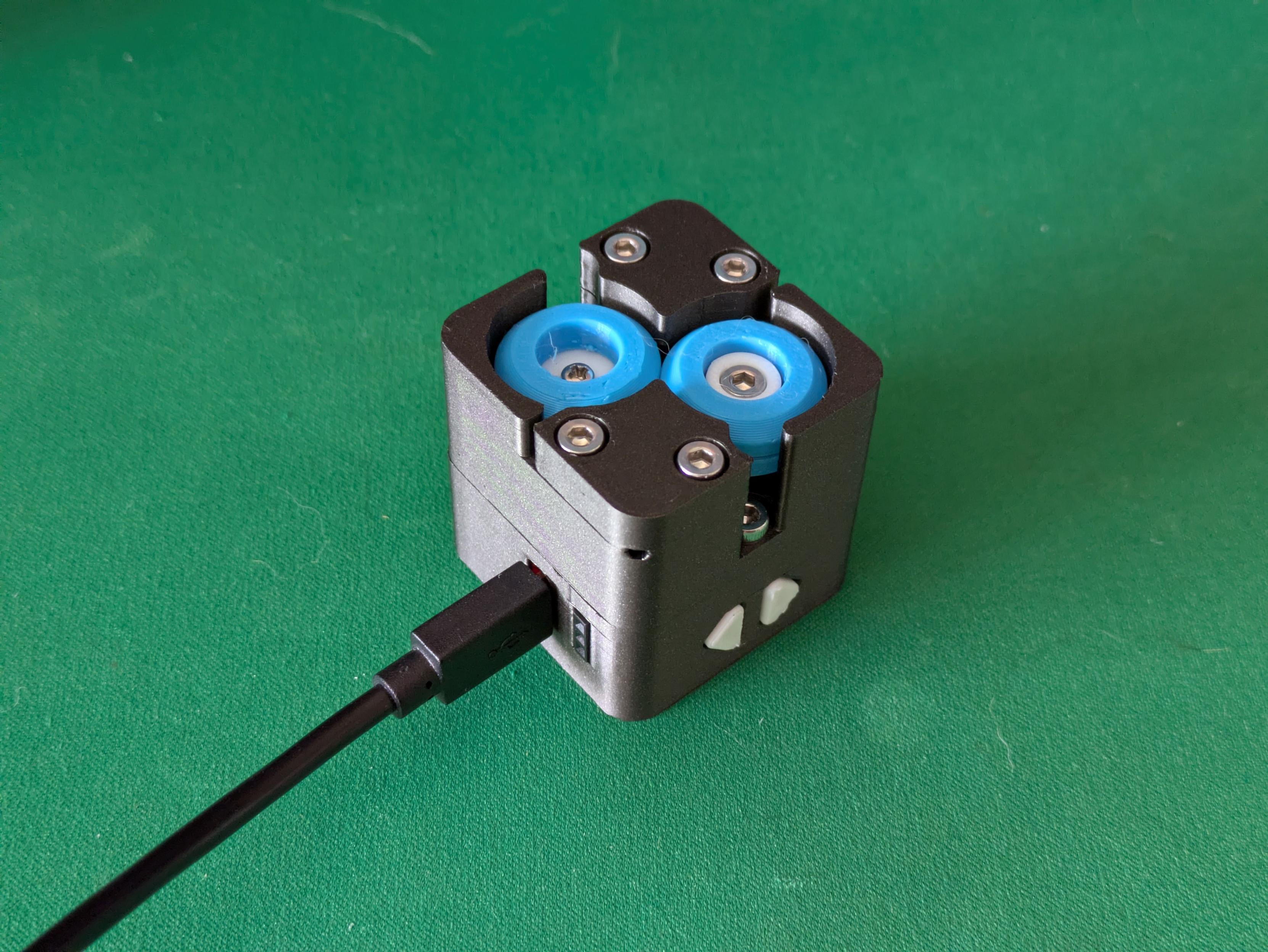
My completely arbitrary obsession with stuffing the entire workings of this thing into an equally arbitrary 4x4x4cm cube because that's how big a square I drew in Rhino 3D on day one of this project is... resulting in a pretty nice little clockwork-looking object.
I'm not loving the "Iron Grey Metallic PLA Metal" filament as much as I would for this though, that might be prettier for more monolithic parts but I think I want something more matte for this project in the end. #3DPrinting
-
My completely arbitrary obsession with stuffing the entire workings of this thing into an equally arbitrary 4x4x4cm cube because that's how big a square I drew in Rhino 3D on day one of this project is... resulting in a pretty nice little clockwork-looking object.
I'm not loving the "Iron Grey Metallic PLA Metal" filament as much as I would for this though, that might be prettier for more monolithic parts but I think I want something more matte for this project in the end. #3DPrinting
Holy crap I got the entire servo's cable in there - and it's powered up and spins when I press the buttons.
It spins the *wrong way*, but that's okay - that USB socket there is the Pro Micro so it's very easily reprogrammable. #Arduino
-
Holy crap I got the entire servo's cable in there - and it's powered up and spins when I press the buttons.
It spins the *wrong way*, but that's okay - that USB socket there is the Pro Micro so it's very easily reprogrammable. #Arduino
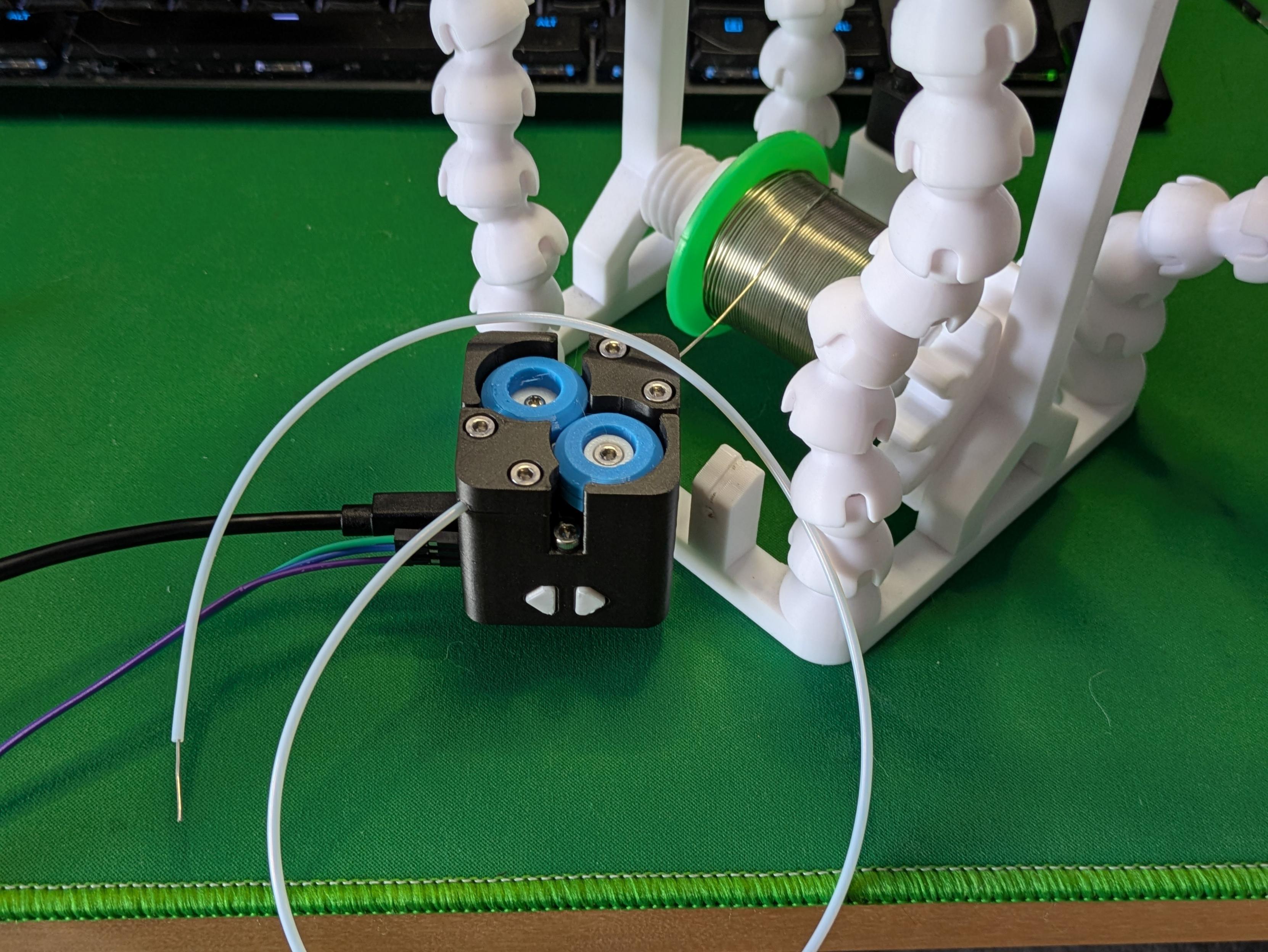
The fully assembled solder feeder, now attached to the front of my #SolderingStation. It replaces the simple little stand I previously used to just bend the end of my solder wire over - that's still attached next to it in case I ever want it again.
I think the trick with this filament is to print with super low layer height, and enable ironing - the top of this thing looks like machined delrin or something.
Last step is finishing the feeder pen itself.
-
The fully assembled solder feeder, now attached to the front of my #SolderingStation. It replaces the simple little stand I previously used to just bend the end of my solder wire over - that's still attached next to it in case I ever want it again.
I think the trick with this filament is to print with super low layer height, and enable ironing - the top of this thing looks like machined delrin or something.
Last step is finishing the feeder pen itself.
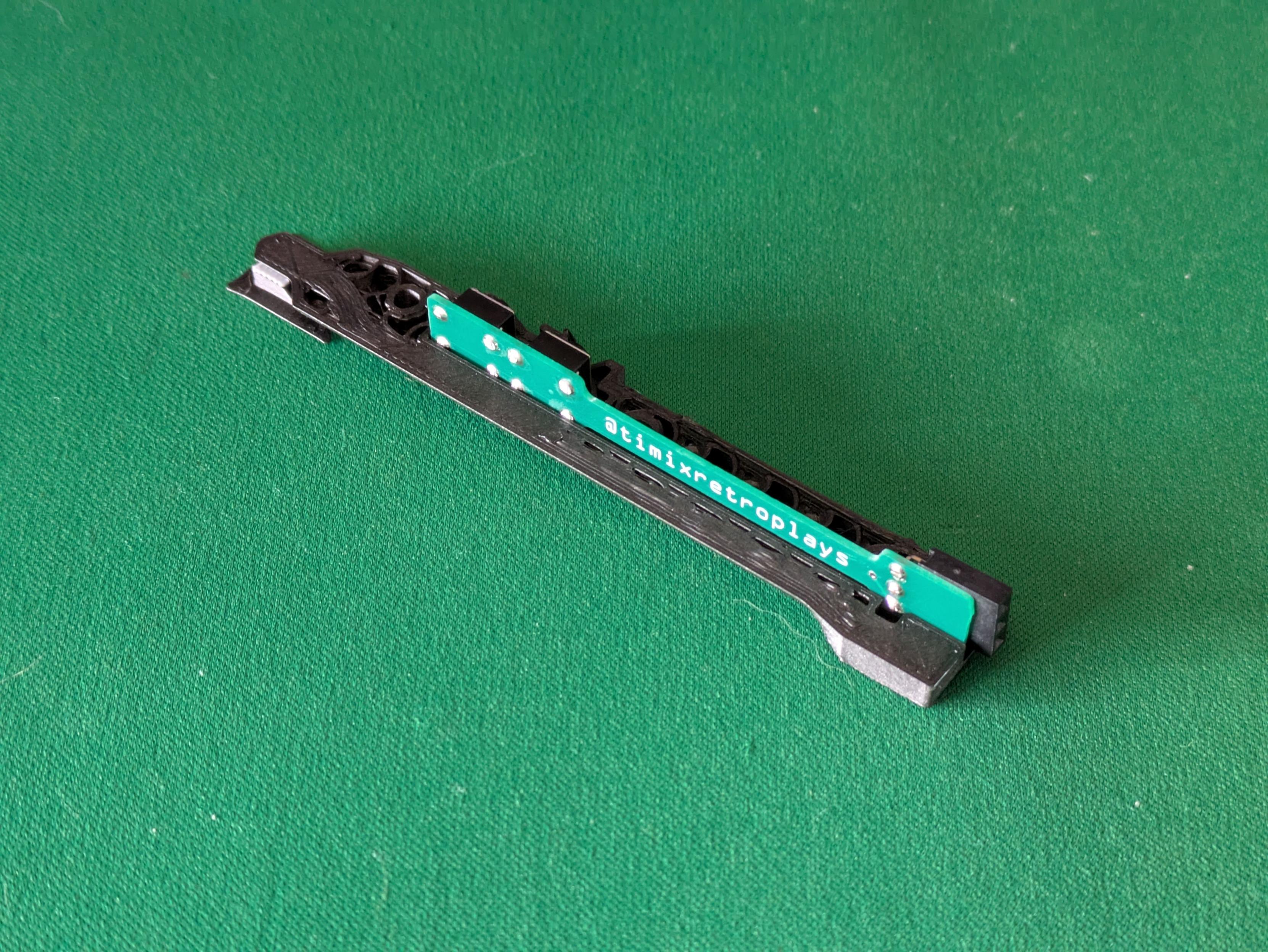
This is a failed print (the other half of the pen lost bed adhesion and became plastic spaghetti), but enough of it worked to confirm I now have the negative space cutout for the feeder pen's electronics correct enough to spend time refining the outside shape.
It started with a roughly cylindrical cross-section, but that immediately made it tougher to print - and it already is a technical print because of the thin walls and large hollows everywhere. Pen v2 will have a simpler form. #3DPrinting
-
This is a failed print (the other half of the pen lost bed adhesion and became plastic spaghetti), but enough of it worked to confirm I now have the negative space cutout for the feeder pen's electronics correct enough to spend time refining the outside shape.
It started with a roughly cylindrical cross-section, but that immediately made it tougher to print - and it already is a technical print because of the thin walls and large hollows everywhere. Pen v2 will have a simpler form. #3DPrinting
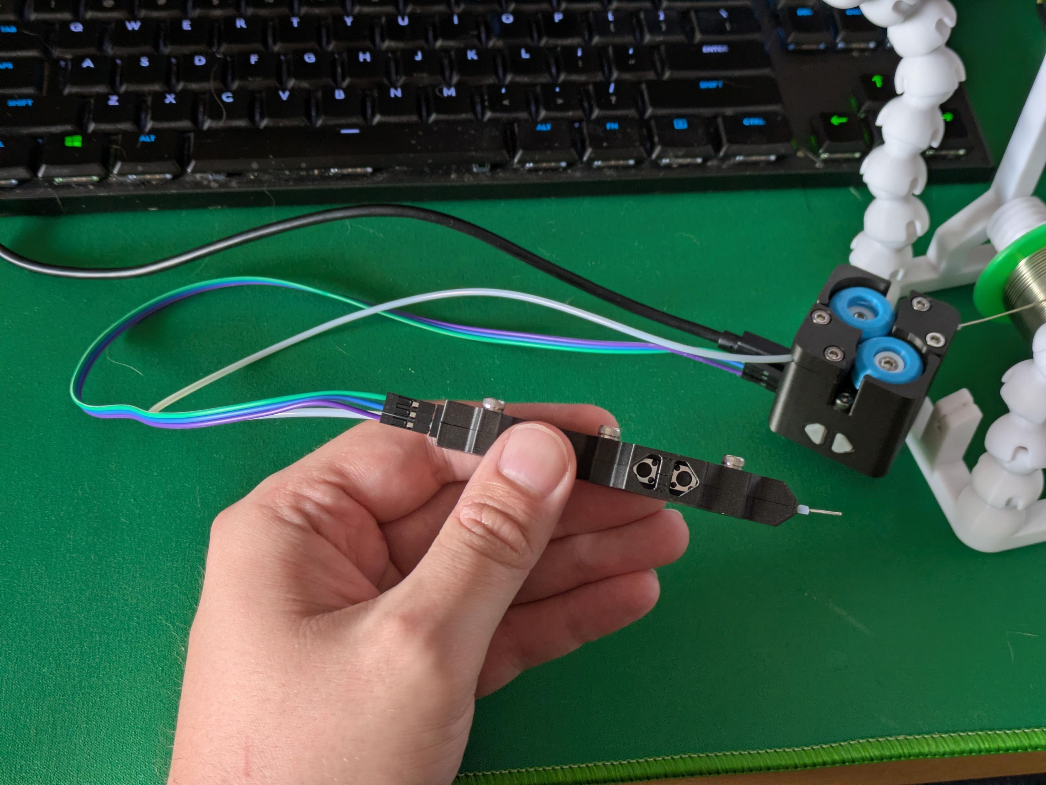
Went for the smarter option of "look at the internals, then design an enclosure around them" rather than "try and stuff everything into an arbitrary tiny shape" and ended up with this extremely functional part. Still need to make the button insert, but this thing absolutely works - press the button, more solder wire appears.
Could I actually be close to - dramatic gasp - finishing a project!? Better yet, as an infrastructure project, this'll make it easier to finish *other* projects as well.
-
Went for the smarter option of "look at the internals, then design an enclosure around them" rather than "try and stuff everything into an arbitrary tiny shape" and ended up with this extremely functional part. Still need to make the button insert, but this thing absolutely works - press the button, more solder wire appears.
Could I actually be close to - dramatic gasp - finishing a project!? Better yet, as an infrastructure project, this'll make it easier to finish *other* projects as well.
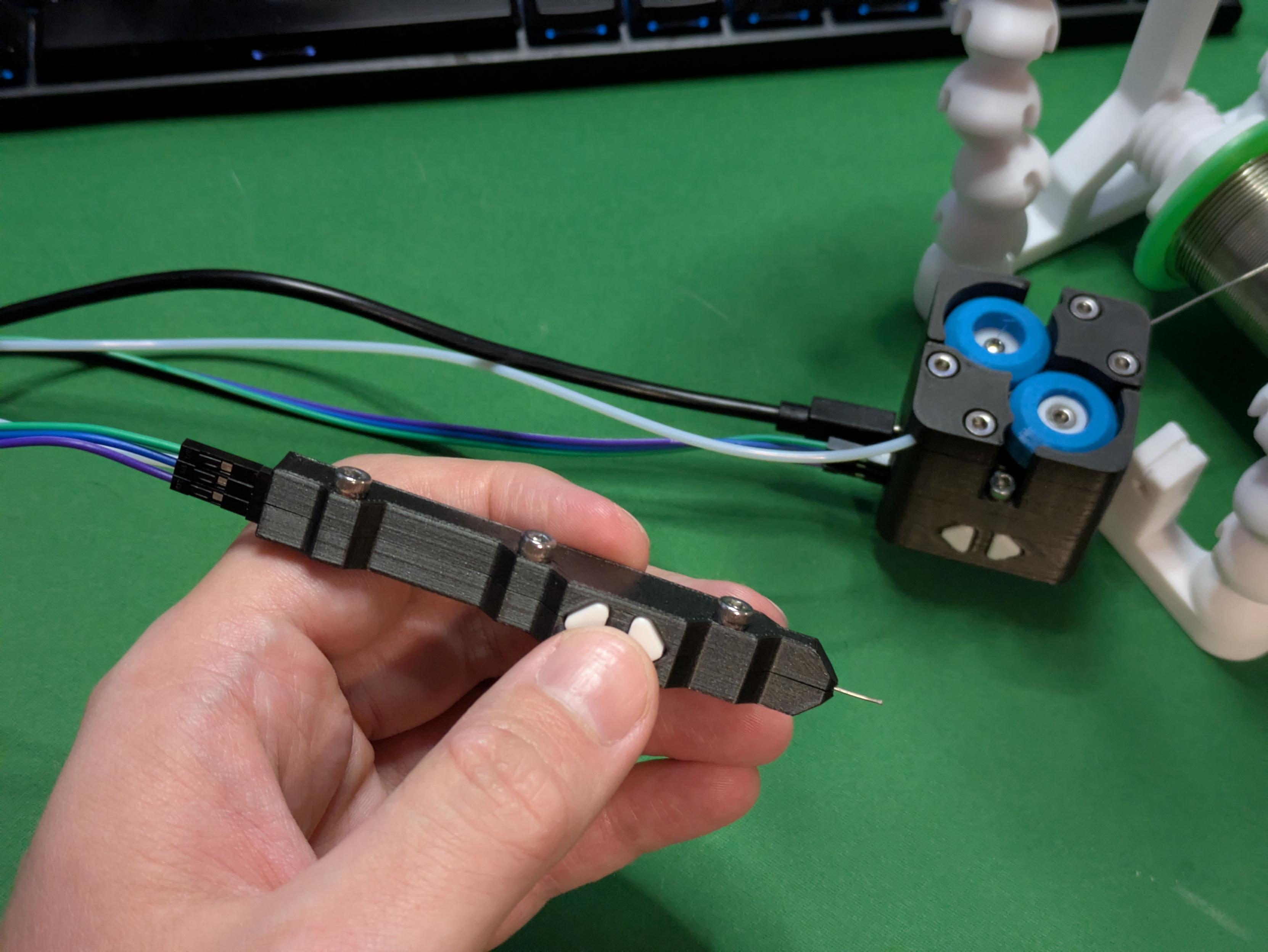
I am now extremely bored of making sub-millimetre adjustments to this tiny button part, but I am pleased to report: it works! Press the button, solder comes out; press the other button, solder goes back in.
The tube is held rigidly and almost completely straight - there is one bend near the nozzle because it has to be off-centre to run underneath the PCB, but I think that might actually help to keep it straight as it deploys.
The solder feeder pen has reached v1.0. #3DPrinting #Arduino #maker

-
I am now extremely bored of making sub-millimetre adjustments to this tiny button part, but I am pleased to report: it works! Press the button, solder comes out; press the other button, solder goes back in.
The tube is held rigidly and almost completely straight - there is one bend near the nozzle because it has to be off-centre to run underneath the PCB, but I think that might actually help to keep it straight as it deploys.
The solder feeder pen has reached v1.0. #3DPrinting #Arduino #maker
Hocus pocus, abracadear; I would very much like the sponge that came with my soldering iron to re-appear
I guess this is a sign it's another thing I should make myself and attach to my soldering station?
-
Hocus pocus, abracadear; I would very much like the sponge that came with my soldering iron to re-appear
I guess this is a sign it's another thing I should make myself and attach to my soldering station?
I usually try not to toot my own horn too much, but I will do so when I'm proud of making something good - and my solder feeder fucking slaps.
This is the first real test done in anger, and there are definite changes to make. It needs a narrower nozzle to get closer to the workpiece, a longer one to straighten the wire better, and a more comfortable handle.
But I will never go back to just feeding solder in by hand. This is 1000% better in every way.
#3DPrinting #Electronics #Arduino #maker