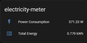
I managed to get Home Assistant to gobble-up energy data from my Hydro Ottawa Elster R1S meter today.
-
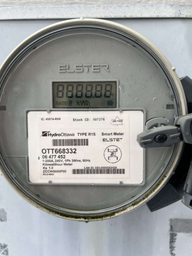
I managed to get Home Assistant to gobble-up energy data from my Hydro Ottawa Elster R1S meter today. I'm using the meter's optical port: it outputs an optical pulse (IR) for every 1mWh or energy consumed, so each pulse-per-minute corresponds to 60W.
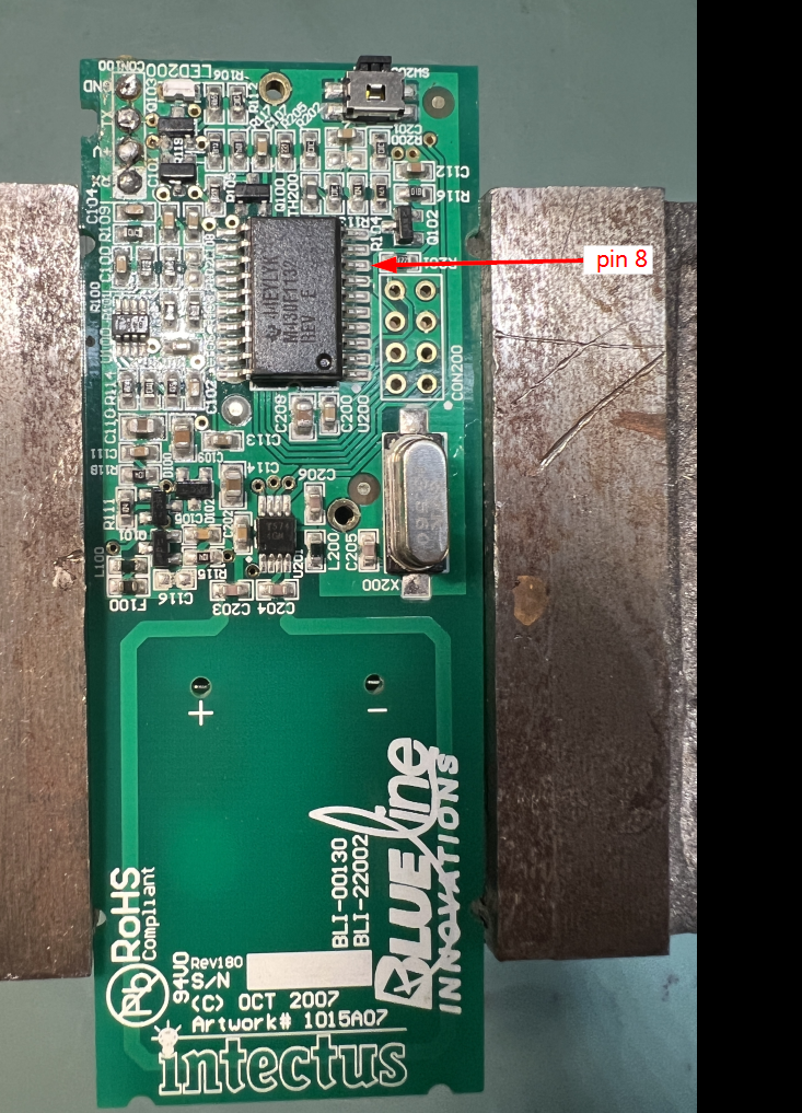
For reading the meter, I'm using the optical sensor and internal circuitry from the Blueline Innovations 'PowerCost Monitor' model BLI-00292. This is barnacled on my meter, installed by Hydro Ottawa a while back. I'm tapping the signal directly at its microcontroller (pin 8). That CCA runs on two 'AA' batteries, but I plan to move its to the basement later this summer, and switch its power source to from the batteries to the +3.3V of the ESP32 CCA itself. I plan to simply running a couple of wires to the phototransistor in the small arm shown in the picture to the ESP32.
Speaking of the ESP32, it reads the pulses via the ESPHome Pulse Meter Sensor (https://esphome.io/components/sensor/pulse_meter/). Works quite well. One also needs a handful or extra parts (NPN transistor, a couple of resistors, filter cap) to convert metered pulses from 0-0.7V to 0-3.3V expected by the ESP32 GPIO pin. #homeassistant #ESPhome -
R relay@relay.mycrowd.ca shared this topic
-
I managed to get Home Assistant to gobble-up energy data from my Hydro Ottawa Elster R1S meter today. I'm using the meter's optical port: it outputs an optical pulse (IR) for every 1mWh or energy consumed, so each pulse-per-minute corresponds to 60W.
For reading the meter, I'm using the optical sensor and internal circuitry from the Blueline Innovations 'PowerCost Monitor' model BLI-00292. This is barnacled on my meter, installed by Hydro Ottawa a while back. I'm tapping the signal directly at its microcontroller (pin 8). That CCA runs on two 'AA' batteries, but I plan to move its to the basement later this summer, and switch its power source to from the batteries to the +3.3V of the ESP32 CCA itself. I plan to simply running a couple of wires to the phototransistor in the small arm shown in the picture to the ESP32.
Speaking of the ESP32, it reads the pulses via the ESPHome Pulse Meter Sensor (https://esphome.io/components/sensor/pulse_meter/). Works quite well. One also needs a handful or extra parts (NPN transistor, a couple of resistors, filter cap) to convert metered pulses from 0-0.7V to 0-3.3V expected by the ESP32 GPIO pin. #homeassistant #ESPhome@ray VERY interested. Also in Ottawa and been trying for figure out how to monitor power for a few years. Can you share more? Parts, schematics, how you attached the barnacle. Would be super appreciative for any bits you are willing to share.
-
@ray VERY interested. Also in Ottawa and been trying for figure out how to monitor power for a few years. Can you share more? Parts, schematics, how you attached the barnacle. Would be super appreciative for any bits you are willing to share.
@ray apparently, according to Gemini, this https://www.digikey.ca/en/products/detail/liteon/LTR-4206/214965 will work, wired to a ESP C3. If you could share more about how you attached your barnacle that would be awesome!
-
@ray VERY interested. Also in Ottawa and been trying for figure out how to monitor power for a few years. Can you share more? Parts, schematics, how you attached the barnacle. Would be super appreciative for any bits you are willing to share.
@gwww I’ll try to document it in a webpage a bit later.
It’s not the prettiest set up right now. I’ll be monitoring for a few weeks before cleaning it up. The secret sauce is the analogue front end of the BLI contraption that sits on the meter. sometimes you can see those in charity shops. I’m guessing it contains a trans impedance amplifier that reads the phototransistor facing the meter, conditions that slightly and sends it to the micro controller pin 8, which is the input of a ADC. I don’t have the schematics for this CCA so I had to probe around. The waveform is only 0.7 V in amplitude and dips to zero with each pulse, with each pulse representing 1mWh of energy. I have a MPN transistor circuit that conditions out from 0 to 3.3 V. -
@gwww I’ll try to document it in a webpage a bit later.
It’s not the prettiest set up right now. I’ll be monitoring for a few weeks before cleaning it up. The secret sauce is the analogue front end of the BLI contraption that sits on the meter. sometimes you can see those in charity shops. I’m guessing it contains a trans impedance amplifier that reads the phototransistor facing the meter, conditions that slightly and sends it to the micro controller pin 8, which is the input of a ADC. I don’t have the schematics for this CCA so I had to probe around. The waveform is only 0.7 V in amplitude and dips to zero with each pulse, with each pulse representing 1mWh of energy. I have a MPN transistor circuit that conditions out from 0 to 3.3 V.@ray thank you!!! I now see how you attached it to your meter
 At least I now know what’s possible. I kept perusing ways to read the radio signal. This IR approach feels very doable.